Current Voltage Relation of Different Memristor Models
| ✅ Paper Type: Free Essay | ✅ Subject: Computer Science |
| ✅ Wordcount: 2065 words | ✅ Published: 26 Mar 2018 |
Abstract: Memristor a two terminal passive non volatile device is considered as the fourth circuit element and can be used in many applications which includes memory, logic and neuromorphic systems. The memristor provides many advantages like scalability, compatibility with CMOS and offers no leakage current. Various models of memristor have been discussed in this paper. The main focus is on the Current-Voltage (IV) relation of different models and its simulation is done in Cadence Virtuoso.
Index Terms- memristor, VerilogA, window function, SPICE, threshold.
- INTRODUCTION
In 1971, L. O. Chua introduced the fourth passive circuit element named memristor which is two terminal non volatile device with a property of variable resistance known as memristance [1]. The memristance provides the relation in the time integrals of voltage and current. Originally, current controlled time invariant memristor is expressed as

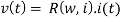
where w is state variable, v(t) is the device voltage, i(t) is the memristor device current, R(w, i) is the memristance and t is the time period.
Since HP labs proclaimed the physical working model of memristor [2], it opens the doors to the new type of electronics. Some of the applications includes logic design [3] [4], memory [5], neuromorphic systems [6].
Different models of memristor have been deigned. Formally designed models does not contain threshold [2] [7] [8] (i.e. resistance changes for any current or voltage). The Threshold Adaptive Memristor model (TEAM )[9] and Voltage Threshold Adaptive Memristor model (VTEAM) [10] models exhibits the threshold current and threshold voltage respectively, are the most efficient models and less computational complexity.
In this paper current-voltage relation of different models is implemented using VerilogA code. Section II describes the different types of memristor models. Comparison of memristor model is provided in section III. The paper is concluded in section IV.
- DIFFERENT MEMRISTOR MODELS
- Linear Ion Drift Model
This is the first and basic model of memristor proposed by HP Labs [3]. This model has width which is splitted in two regions as shown in Figure 1. The region with width w is doped with positive oxygen ions (originally TiO2) and has low resistance therefore is more conductive and other side is undoped. Each region is modeled with resistor (in series). Various assumptions are considered i.e. ohmic conductance, uniform field and average ion mobility.

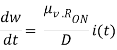
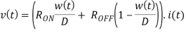
RON is the resistance at w(t) = D and ROFF is the resistance at w(t) = 0 The state variable w(t) is bounded within the interval [0,D]. To prevent w from going beyond the physical dimensions of the device, the derivative of w is required to multiply by the window function.
The IV relationship curve of linear ion drift model of memristor for sinusoidal input is shown in figure 2.
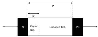
Figure1: HP memristor model [1]
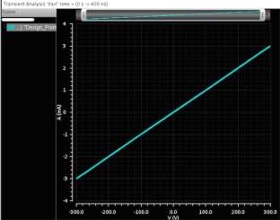
Figure 2: IV curve of linear memristor model with 2-window function.
(frequency=20MHz,source amplitude=0.003A, Ron=100ohm, Roff=2e5ohm, μv=10e-14m^2/Vs, D=10e-9m, P_coeff=2, initial state=0.5, j=1, w_multiplied=1e9, P_window_noise=1e-18)
- Non Linear Ion Drift Model
Although the linear ion drift model of memristor is simple and satisfies the basic memristor equations. But as per the experiments of the fabricated device, it behaves differently i.e. it is highly non linear [11] [12]. The non linearity is desirable for logic circuits, therefore another memristor model have been proposed based on experimental results concluded in [11]. A model is [13] proposed. The relation between current and voltage for this model is

Where α,  ,
,  are known as fitting parameters and parameter n describes the influence of state variable (w) on the currents. . Here, the state variable w is normalized within the interval [0,1]. The model shows asymmetric switching behavior, in a way that during the ON state, w is near one and the first term of, is the dominant part of the current, which is a tunneling phenomenon. During the OFF state, w is near zero and the second term, has the dominant part of the current, which is similar to an ideal diode equation. The state variable differential equation is written as

where a, m are constants, f(w) is the window function and m is an odd integer. And there is a nonlinear dependency on voltage.
The IV characteristics of this model is shown in figure 3.
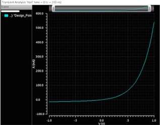
Figure3: IV curve of non linear ion drift model with 2-window function
(frequency=20MHz,source amplitude=1V, P_coeff=1, initial state=0.5, j=1, Alpha=2, Beta=9, C=0.01, g=4, n=13, q=13,a=4, w_multiplied=1, P_window_noise=1e-18)
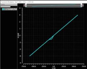
Figure 4: IV curve of simmons tunnel barrier model.
(frequency=20MHz,source amplitude=0.003A, Ron=100ohm, Roff=2e5ohm, D=3e-9m, initial state=0.5, aon=2e-9,aoff =1.2e-9, ion=8.9e-6, ioff=115e-6,con=40e-6, coff=3.5e-6,b=500e-6,Xc=107e-12 w_multiplied=1e9, P_window_noise=1e-18)
- Simmons Tunnel Barrier Model
Another model having more accuracy than previous discussed model was proposed in [14]. The assumptions of this new model includes non-linearity and asymmetric switching behavior because of an exponential dependency of movement of ionized dopants i.e. changes in state variable. Physical model of this type has a resistor in series with electron tunnel barrier. The simmons tunnel barrier width x, is the state variable. So the derivative of x can be represented as oxygen vacancy drift velocity, and is:
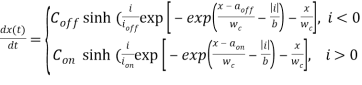
where b, con, coff, ion, ioff, aon, aoff are known as fitting parameters. Con is always greater than coff and they both effect the magnitude of change of x. The parameters ioff and ion define the current threshold. Another parameter aoff and aon gives the upper and lower bounds of x respectively. Within the range defined, the derivative of state variable x, is significantly smaller than state variable itself. Therefore, there is no need of window function that is the biggest advantage of this model.
According to the simmons tunnel model, the relation between voltage and current can be expressed as:

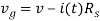
Where V is applied voltage and v is internal voltage of the device (it is not necessary that both voltages are equal [15] ).
Based on the fitting parameters, the IV characteristics curve of the simmons tunnel barrier model is shown in figure 4.
- TEAM Model
Before 2013, it was claimed that Simmons Tunnel Barrier model is the most accurate memristor model but it too has some limitations of complication, unexplicit relation in voltage and current and is not in general. Therefore a model with accuracy and simpler expressions is the main demand.
The TEAM ( Threshold Adaptive Memristor model) is proposed by Shahar Kvatinsky [16]. This is simple and general model, physically similar to predefined model. Some assumptions can be made for analysis and for computational efficiency.
Based on assumptions, state variable derivative of this model is expressed as
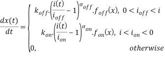
where aon,aoff, kon,and koff are constants (koff is positive and kon is negative). foff(x) and fon (x) are the window functions, depends on state variable x.
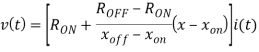
by assuming the current voltage relation is same as memristance of memristor which changes linearly in x. Therefore,
but if Simmons Tunnel Barrier model is assumed then memristance changes exponentially and given as
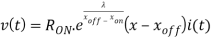
where λ is the fitting parameter. The parameter Ron and Roff are resistances at bound and satisfies

By tuning different parameters of the model, the VI curve of this model is showm in figure11.
According to [9], it is claimed that the accuracy of TEAM model is more enough having mean error of 0.2%.
- VTEAM Model
Many experiments on memristive devices shown the existence of threshold voltage [2] [16] [17] instead of threshold current. Therefore, Shahar Kvatinsky designs the new model i.e. VTEAM model [10] (Voltage Threshold Adaptive Memristor model), contains threshold voltage. Another reason for the existence of this model is that a memristor exhibiting threshold voltage is more desirable than the threshold current in many applications of memory and logic [10].
The advantages of TEAM model (i.e. general, accurate, simple, designer friendly) combines with threshold voltage in spite of threshold current gives the VTEAM model.
Similar to the state variable derivative of TEAM model, the state variable derivative of VTEAM model is

where koff, kon αoff and αon are constants. Parameters voff and von are threshold voltages. The window functions fon and foff defines the dependency of state variable derivative on state variable w.
for VTEAM model, the current voltage relation is not properly defined but the linear dependency of state variable and resistance can be attained, from where current voltage relation is
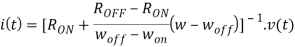
where woff and won gives bounds of state variable w.
The curve for the IV relation of VTEAM memristor model is depicted as in figure 6.
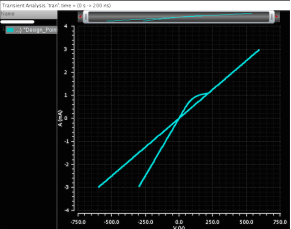
Figure 5: IV curve of TEAM model with 4-window type.
(frequency=20MHz,source amplitude=0.003A, Ron=100ohm, Roff=2e5ohm, μv=10e-14m^2/Vs, D=10e-9m, P_coeff=2, initial state=0.5, j=1.5, aon=2.3e-9, aoff =1.2e-9, ion=-1e-6, ioff=1e-6, kon=-8e-13, koff=8e13, xon=0, xoff=3e-9, aon=3,aoff=3, Xc =107e-12 w_multiplied=1e9, P_window_noise=1e-18)
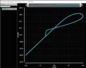
Figure6: IV curve of VTEAM model without window function.
(frequency=20MHz,source amplitude=1V, Ron=100ohm, Roff=2e5ohm, μv=10e-14m^2/Vs, D=10e-9m, P_coeff=2, initial state=0.5, j=1.5, aon=2e-9, aoff =1.2e-9, von=-0.2 voff=0.02, kon=-8e-13, koff=8e13, xon=0, xoff=3e-9, aon=3,aoff=3, Xc =107e-12 w_multiplied=1e9, P_window_noise=1e-18)
- COMPARISON
Comparison of different models of memristor is listed in table1.
|
Model |
Linear Ion Drift |
Non Linear Ion Drift |
Simmons Tunnel Barrier |
TEAM |
VTEAM |
|
State variable |
0≤ w≤ D |
0≤ w≤ 1 |
aoff ≤ x≤ aon |
xoff ≤ x≤ xon |
woff ≤ x≤ won |
|
VI relation |
Explicit |
Explicit |
Ambiguous |
Explicit |
Explicit |
|
Generic |
No |
No |
No |
Yes |
Yes |
|
Control mechanism |
Current |
Voltage |
Current |
Current |
Voltage |
|
Accuracy |
Lowest |
Low |
High |
Sufficient |
Highest |
|
Threshold |
No |
No |
Practically |
Yes |
Yes |
|
Matching Memristive system |
Yes |
No |
No |
Yes |
Yes |
Table 1: Comparison between diffent memristor models.
- CONCLUSION
In this paper, different models of memristor- linear ion drift model, non linear ion drift model, simmons tunnel barrier model, TEAM model and VTEAM model are described. Moreover the VI characteristics of each model is simulated. The VI curve for VTEAM model is most efficient and desirable. Also VTEAM and TEAM models are simple, general and accurate.
The VI characteristics of each model is implemented by using verilogA code [18] because of its effiency regarding computational time than SPICE model.
REFERENCES
- L. O. Chua, “Memristor – The Missing Circuit Element,” IEEE Transactions on Circuit Theory, Vol. 18, No. 5, pp. 507-519, 1971.
- D. B. Strukov, G. S. Snider, D. R. Stewart, and R. S. Williams, “The Missing Memristor Found,” Nature, Vol. 453, No. 7191, pp. 80-83, 2008.
- G. Snider, “Computing with hysteretic resistor crossbars”, Applied Physics A, Material Science Process, vol. 80, page 1165-1172, 2005.
- S. Kvatinsky, E. G. Friedman, A. Kolodny, and U. C. Wieser, “Memristor-based IMPLY logic design procedure”, Proceedings IEEE International Conference Computational Design, page 142-147, 2011.
- G. M. Huang, Y. Ho, and P. Li, “Nonvolatile memristor memory: Device characteristics and design implication”, Proceedings IEEE International Conference Computer Aided Design, page 485-490, 2009.
- A. Ayatollahi, A. Afifi, and F. Raissi, “Implementation of biologically plausible spiking neural network models on memristor crossbar-based CMOS/Nano circuits,” Proceedings Eur. Conference Circuit Theory Design, page 563-566, 2009.
- E. Lehtonen and M. Laiho, “CNN Using Memristors for Neighborhood Connections,” Proceedings of the International Workshop on Cellular Nanoscale Networks and their Applications, pp. 1-4, February 2010.
- M. D. Pickett et al., “Switching Dynamics in Titanium Dioxide Memristive Devices,” Journal of Applied Physics, Vol. 106, No. 7, pp. 1-6, October 2009.
- S. Kvatinsky, A. Kolodny, U. C. Wieser, and E. G. Friedman, “TEAM: ThrEshold Adaptive Memristor Model”, IEEE Transactions on circuits and Systems 1: Regular Papers, page 211-221, 2013.
- S. Kvatinsky, M. Ramadan, E. G. Friedman, and A. Kolodny, “VTEAM – A General Model for Voltage Controlled Memristors”, IEEE Transactions on Circuits and Systems, page- 1-5, 2014.
- J. J. Yang, M. D. Pickett, X. Li, D. R. Stewart, and R. S. Williams, “Memristive switching mechanism for metal/oxide/metal nanodevice”, Nature Nanotechnology, page 429-433, 2008.
- R. S. Williams, and D. B. Strukov, “Exponential ionic drift: Fast switching and low volatility of thin- film memristor”, Applied Physics A. Material Sci. Process., page 515-519, 2009.
- M. Laiho, and E. Lehtonen, “CNN using memristors for neighborhood connections”, Proceedings International Workshop Cell. Nanoscale Network Their Applications, page 1-4, 2010.
- D. B. Strukov, J. J. Yang, M. D. Pickett, and J. L. Borghetti, “Switching dynamics in titanium dioxide memristive devices”, Journal Applied Physics, page 1-6, 2009.
- J. G. Simmons, “ Generalized formula for the electric tunnel effect between similar electrodes separated by thin insulating film”, Journal Applied Physics, page 1793-1803, 1963.
- A. Chanthbouala, et al., “A Ferroelectric Memristor.”, Nature materials, page 860-864, 2010.
- D. Liu, et al., “Analog Memristors Based on Thickening/Thinning of Ag Nanofilaments in Amorphous Manganite Thin Films”, ACS Applied Materials & Interfaces, page 11258-11264, 2013.
Cite This Work
To export a reference to this article please select a referencing stye below:
Related Services
View all


DMCA / Removal Request
If you are the original writer of this essay and no longer wish to have your work published on UKEssays.com then please click the following link to email our support team:
Request essay removal