DC Motor Speed Control
| ✅ Paper Type: Free Essay | ✅ Subject: Engineering |
| ✅ Wordcount: 1280 words | ✅ Published: 30 Aug 2017 |
- Abstract
The point of this paper is to comprehend the attributes of open loop and close loop speed control for a DC engine. It additionally intends to demonstrate the properties of a PID Controller.
- Introduction
Open loop and close loop control are two unique sorts of controlling the speed of the engine we constructed. These two sorts of control each have positive points and negative points, which we will attempt to research all through this paper.
Most importantly, an open loop system works regardless of the output of the function. In restriction, a close loop control system react depending on the input and output values. Utilizing an Arduino microcontroller, we will run tests on this motor by changing some variables. This permits us to concentrate data about the responses of the control system.
P, D and I remain for: proportional gain, integral gain and derivative gain. Their particular elements show up in the following section.
- Theory
The transfer function of a first order system is given by the equation:
: .
.
Knowing that (k/a) the final value in RPM, and that the time constant is 1â„a. The transfer functions of the system can then be determined.
In principle, corresponding, integral and derivative gain cooperate with a specific end goal to keep up the output to a set value. The corresponding gain applies an exertion that is relative to how far the value is from the set esteem. In any case, the nearer the set and value are the less exertion it applies on the system. The basic pick up’s part is to try and out the time spent on each side of the set point. Last, the derivative gain controls the overshoot and goes about as a dampener when the value changes violently.
- Results
- Open loop test
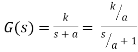
Fig 1: Open loop test 1
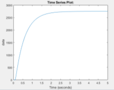
Fig 2: Test 2 time series plot
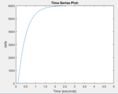
Fig 3: Test 3 time series plot
Fig 11: Simulink model of open-loop system


The realistic information demonstrates a delay of 0.1s and the time taken to achieve 63% of the last esteem is 0.5s for each test. So the time steady is 0.4s for each test. At that point the transfer function of each of these system can be resolved:
 Â ,
 ,
  ,
,
 .
.
When rescaled to RPM units, these transfer functions are all equal to:

Toward the finish of this section, one noteworthy weakness of open loop control system shows up. The open loop system doesn’t take a gander at the output value, so it can’t correct itself. Despite the fact that the system works, it depends for the most part on the client’s involvement to conform the PID controls to the correct qualities to acquire the best outcomes. The proportionnal gain role is to direct the final value that the system comes to (the higher the gain, the nearer to the set value the systeme will be).

- Closed loop system test
In the test where kp=1 that appeares on figure 4, the set point was 1000 RPM. Not surprisingly for this low estimation of the proportionnal gain, the last value is just around 4000 RPM. So we will increse the Kp to see what it does to the system.
At the point when the estimation of kp expands, the exactness of the system get higher. On figure 4 the red bend demonstrates the outcomes for kp=2, the last RPM esteem has expanded to 6000 with an overshoot to 8000. Figure 4 obviously demonstrates that the greater kp is, the nearer the last esteem is from the coveted set point. Expanding the estimation of the proportionnal gain enhances the precision of the close loop system.
The system begins to sway unmistakably for a proportionnal pick up estimation of 15, with a time of around 0.5 seconds (reference: figure 4, kp=15).
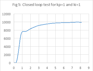 On figure 5, the system seems to stabilize at 1 second and then reaches the set point value of 10000 RPM a around 8 seconds
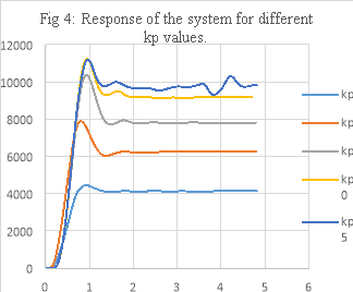 . Let’s try to understand what is the relationship between the Kp and the Ki.
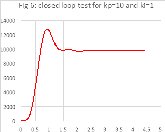
On figure 6, the system goes into overshoot before backpedaling to the fancied estimation of 10000 RPM. The framework takes roughly 2 seconds to settle to its last value.
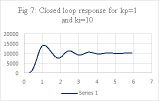
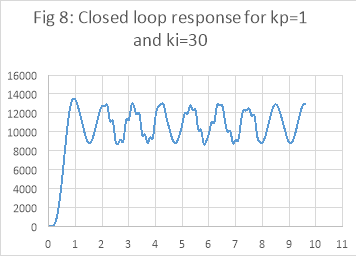
Figure 7 demonstrates se reaction of thew motor with kp set to 1 and ki set to 10. It is recognizable that for a higher ki value, the reaction (in RPM) is swaying around the chosen value (10000 RPM for this situation), expanding its exactness with each period.
On the off chance that ki is expanded to a higher value, the oscillation don’t enhance in exactness as observed on figure 8.
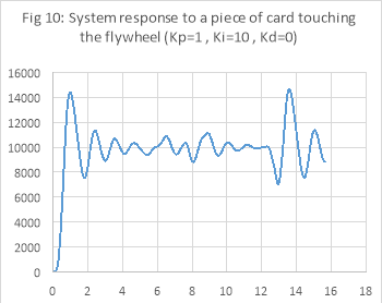
After around 5 seconds, the Dc motor has balanced out; At this point, the card touches the flywheel (see figure 10). The reaction is prompt, and the system tries to remunerate the loss of RPM has returned to the sought estimation of 10000, which it settles again around 7 seconds after the card touched the framework. This test demonstrates the fundamental favorable position of a close loop system, which is that if the output is changed, the input changes likewise to go back to the initial value.
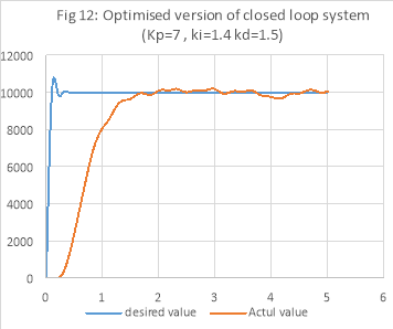
these tests comprehended the parts of every PID control. By tweaking the numbers, it is conceivable to streamline the framework so that the reaction has a negligible overshoot and in addition the speediest settling time conceivable. By abusing the outcomes, unmistakably a shut circle control framework is the best for this circumstance. Figure 12 demonstrates the best outcome acquired in the lab for set estimations of the PID controller
As it shows on figure 12, expanding the estimation of the derivative gain keeps the system from overshooting. With this estimation of the proportional gain, the DC motor can settle rapidly (in around 1.5 seconds) around the estimation of 10000 RPM. To further build the exactness of the motor, the integral gain was set to 1.4. This empowers the system to make little oscillation around 10000 RPM without losing any exactness.
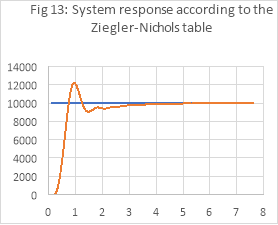
Planning a PI controller in like manner to this table brought about a system that has great attributes: little overshoot, quickly revised, quick settling time and just a small error on the last estimation of the system.This table is exceptionally helpful with regards to designing the motor.
Be that as it may, outlining a PID controller with this table is trickier as the derivative gain affects the way the system carries on. It can dampen the motor excessively, or take a little unsettling influence for a major issue and the system won’t be as productive. The key is not to utilize a lot of the derivative.
- Conclusion
In conclusion, the less complex outline of the open loop system makes it simple and modest to make, all things considered. Notwithstanding, the way that open loop system don’t adjust to unsettling influences in the output is a noteworthy disadvantage. The adequacy of these system depends on the qualities picked by the user for for proportional, integral and derivative gains.
close loop system are vastly improved at keeping up a desired target, for this situation the speed of the engine. By tweaking the estimations of every parameter of a PID controller, it is for all intents to make the system do precisely what it is intended to.However, the three type og gain must be set for each exact system, which makes outlining the close loop system more complex to do.
- References
Document on moodle
“Open loop systems” http://www.electronics-tutorials.ws/systems/open-loop-system.html
“Understanding D in PID control” http://www.controleng.com/search/search-single-display/understanding-derivative-in-pid-control/4ea87c406e.html
electrical4u, 2013. Speed Control of DC Motor. [ONLINE] Available at: http://www.electrical4u.com/speed-control-of-dc-motor/. [Accessed 9 February 2017].
Bishop, R.H. and Richard C. (Richard Carl) Dorf (1998) Modern control systems. Available at: https://capitadiscovery.co.uk/greenwich-ac/items/337549?query=Modern+control+systems&resultsUri=items%3Fquery%3DModern%2Bcontrol%2Bsystems (Accessed: 17 February 2017).
Cite This Work
To export a reference to this article please select a referencing stye below:
Related Services
View all


DMCA / Removal Request
If you are the original writer of this essay and no longer wish to have your work published on UKEssays.com then please click the following link to email our support team:
Request essay removal