Effect of Simultaneous Exposure to Corrosion and Fatigue on Bond Strength Between CFRP and Steel Plates
| ✅ Paper Type: Free Essay | ✅ Subject: Engineering |
| ✅ Wordcount: 5107 words | ✅ Published: 18 May 2020 |
EXPOSURE TO CORROSION ND FATIGUE ON BOND STRENGTH BETWEEN CFRP AND STEEL PLATES

5.1 INTRODUCTION
Corrosion is a serious problem in civil infrastructures, which can significantly jeopardize the structural integrity of the element. Damaged caused by corrosion can dramatically be exaggerated when combined with an existence mechanical loading (1).
Last few decades many studies carried out on repairing and retrofitting civil infrastructures using the advanced composite materials (1) (2) (3) (4) (5) (6). It has been shown that fiber-reinforced polymer (FRP) composite materials has had a dramatic impact on civil engineering techniques. Adhesively-bonded composites material has led to improve both structural integrity and sustainability performance of these structures. Thorough theoretical and practical studies have been adopted on CFRP to repair steel structures [4, 7, 10, 11, 13, 14, 19, 20-29]. Bond durability has been a focal concerned issue for many researcher [4, 7, 10. 11] due to its effect on the resultant panel. However, studies in this area performed so far have been limited and many issues lack clarification. For example, most studies have studied the behaviour of the bond durability when it has been affecting by either the environment or the loading, however, in most cases that these two factors are existing together in the same time.
As such, and due to the lack of knowledge in studying the effect of the simultaneous effect of corrosion and fatigue on the steel repaired with CFRP. This chapter presents an experimental study into the combined effect of both a severe environment and mechanical loading (static or fatigue) on the steel repaired with CFRP. The attacking of a severe environment represented by 3.5 % NaCl stimulated sea water at 60 0C, which next will generate the required corrosion. However, these circumstances have to be accompanied with the mechanical loading (static or fatigue). As this is important since steel structures are widely used in conditions where the effect of both environment and mechanical loading are existing. In order to meet these requirements, an experimental design has been accomplished, a description of the experimental set-up and the methodologies that were developed to determine the simultaneous effect of corrosion and fatigue on CFRP/steel repairs is given in Section 5.2. Section 5.3 describes an experiment test that was performed to determine the diffusivity rate of normal modulus CFRP laminates. An experimental investigation into the bond durability of CFRP repairs to steel plates under the combined exposure of corrosion and fatigue is presented in Section 5.4. Section 5.5 presents the results of an experimental investigation performed to evaluate the CFRP/steel bond quality prior to testing. Finally, Section 5.6 discusses new finding made in section 5.4 that aspects of the classical lap joint theory (that underpin the recommendations given in the PABST program and presented in the US Composite Materials Handbook CMH-17-3G [1, 2] are invalid.
5.2 Set Up and Experimental Design
The test design developed to investigate the combined effect of the environment and the mechanical loading on bonded CFRP steel joints is shown in Figure 1. This design lay out, which is given in [3], provides exposure to the corrosive environment while the specimen undergoes mechanical loading, see Figure 5.1(a). Some changes have accomplished to the design in [3] with respect to the specimen size and the steel mechanical properties. This set up briefly consists of two corrosion chambers that are firmly connected with the machine and hold the specimen inside. The main chamber, which was made of acrylic, performs two crucial jobs. One is holding the solution prepared for this test program which is 3.5 % NaCl artificial sea water at a maximum temperature of 60 0C. This chamber also contains a metal grip which penetrates through its bottom and connects the specimen to the lower grip of the fatigue machine. This chamber was not covered at the top as this allows the specimen to be directly connected to the upper grip of the machine. It also has two apertures, upper and lower apertures used for solution inlet and outlet respectively.
Circulation of the inner solution which is inside the chamber was continuously needed to maintain the temperature as same as the solution in the water path as indicated in Figure 5.1(d), to this end a heater and a pump were used to circulate the water and control its temperature inside the chamber. An additional chamber, which was made of metal, embraced the main chamber. The role of this “second” chamber, which is labelled number 7 in Figure 5.1(b), was to guarantee no solution leakage and to support the whole rig inside the upper and lower machine grips.

Figure 5.1: Experimental design for the simultaneous effect of environment and load: a) A schematic view of the design set-up [3], b) experimental set-up of the durability test c) a view of the secondary chamber of the rig, and d) the water bath which contains water pump and heater.
In order to enable fatigue testing to be performed in a normal way, while the specimen is immersed totally in the environment, an additional grip was used to handle the specimen from one end and to connect it to the fatigue machine from the other. The grip that was submerged completely in the environment was made of stainless steel so as to resist the anticipated corrosion, see Figure 5.1(c). The test specimens were designed to fit inside the rig and as such were designed to be a maximum of 400 cm long. The specimens also had a hole at one end in order to be gripped inside the chamber. Thus the bearing capacity of this member was a critical design consideration.
5.3The Moisture Uptake Investigation for Normal Modulus CFRP Plates (Diffusivity Rate)

Figure 2: Configuration of double lab joint specimen (not to scale)
This was determined as per the standard test, as detailed in ASTM D5229. To this end, 10 CFRP plates specimens of the dimensions (50 x 200 x 1.2 mm) were prepared as shown in Figure 5.3. The dimensions were chosen to be the same as CFRP plates in Section 5.2.


Figure 5.3: Normal modulus CFRP plates
Two different exposure temperatures, viz, 20 and 50 0C, were utilised. The weight measurements were done at various time intervals every 24 hour for the first week and every 2 days for the next 12 days. This was done by removing the specimen from the water tank, and extra water on the surface was dried using clean tissues. The change in weight as a percentage was plotted against the square root of time (√t), where t is the time in days. By assuming that the diffusion occurs in one dimension, and ignoring the thickness effect, such as the case represented by a thin film of a thickness adsorbing a fluid according to Fick’s law with constant surface boundary conditions, the amount of diffusant, M2, taken up by the sheet in a time, t, is given by [5, 23], Once the moisture uptake become constant then this is the time that the sea water requires to penetrate the CFRP plate and reach the interface in between the composite and the adhesive, see Figure 5.5. Accordingly, by using equation (1), the diffusivity rate of normal modulus CFRP material has been calculated.
Here h, l, and w are thickness, length, and width of the panel, M1 and M2 are the equilibrium sorption attained theoretically at time t1 and t2, respectively. It was found that the times required for normal modulus CFRP laminate immersed in 50 0C and 20 0C to reach their maximum moisture weight gains were approximately 10 to 13 days and 15 to 17 days respectively. This is shown in Figure 5.5, which shows the theoretical moisture uptake behaviour predicted using Fick’s second law of diffusion [6, 7]. Subsequently, the coefficients of diffusivity were 2.52 x10⁻⁹ and 3.00 x 10⁻⁹ for 20, 50 0C respectively see Table 5.1.
 These specimens were first dried in an oven for 24 hours and weighed using a digital balance with precision to 0.01g as shown in Figure 5.4 (a) and (b) respectively. They were then immersed in the environment which was 3.5% NaCl simulated sea water see Figure 5.4 (c) and (d).
Figure 5.4 Steps indicating moisture uptake test, a) Drying step in an oven, b) specimen weighing, c) specimen in sea water, d) specimen in the environment (20 and 50 0C 3.5% NaCl)

Figure 5.5 Moisture uptake curve for the CFRP laminates immersed in sea-water
Table 5.1: Characteristics of moisture uptake and the diffusivity coefficient of normal modulus CFRP laminate at 20 and 500C 3.5%wt NaCl .
|
The Environment |
Temperature (0C) |
Maximum moisture Uptake (%) |
Coefficient of Diffusion (mm2/s) x 10-9 |
|
3.5 %wt NaCl |
20 |
1.03 |
2.52 |
|
3.5 %wt NaCl |
50 |
1.7 |
3.00 |
5.4 The Bond Durability Experiment
5.4.1 Test Configuration and Material Properties
CFRP/steel double overlap fatigue specimens (dofs) with dimensions shown in Figure 5.6 were fabricated. These specimens consisted of two 350 grade mild steel inner adherends bonded to normal modulus (E = 200 GPa) CFRP outer adherends. The dimensions of the steel inner adherents were: 180 mm long, 50 mm width and 5 smm thick. The size and configuration of specimens were designed according to AS1391 specifications (2001) and designed to fit in the designed rig and be tested under fatigue load.
The two outer adherends were a layer of CFRP composite, MBRACE laminate normal modulus (E = 210,000 MPa), 200mm long, 50 mm wide and 1.4 thick see Figure 5.7(b). A CFRP laminate was used since it is perhaps the most commonly used composite material used in the repair of steel infrastructure.
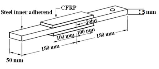
Figure 5.6 Schematic design of the CFRP/steel double lap joint.

Figure 5.7: Material photos (a) Mixed structural adhesive (b) CFRP laminate.
The adhesive used in this test was the epoxy resin adhesive (Araldite 420 A/B) see Figure 5.6(a). Araldite 420 has widespread applications in bonding various structural substances such as metal, wood, rubber, composites and many plastics. This is attributed to its typical properties, namely, design flexibility, extremely tough but resilient, relative rigidity, and its cost-effective characteristic, in addition to it’s room temperature curing property [4] The manufacturer outlines that the CFRP laminate has a tensile strength and an elastic modulus of 3,300 MPa and 210 GPa respectively. A Poisson’s ratio ν12 of the laminate was assumed to be 0.35, which is a typical value for this type of adhesive [8, 11].
5.4.2 Specimens Preparation
The dofs specimen geometry was originally proposed in [9] since it closely simulates the stress state in both the repair and the adhesive associated with a composite repair to a cracked metal structure.
As recommended in [10] surface sandblasting was used as a mechanical surface preparation technique to roughen steel surface. Surface roughness helps to increase the surface area, which enhances adsorption and interlocking, thereby facilitating adhesion and bonding. The steel surface was abrasively sandblasted by subjecting it to an accelerating media (16-grit sand) through a blasting nozzle by means of compressed air. (Note that the gun should be held away about 5 cm from the surface at 450 angles). The (roughened) steel surface was then cleaned first by compressed air to remove the dust sand particles and secondly with acetone using a clean brush. Roughening the surface (sandblasting) and then wiping it with chemical solvent (acetone) can produce a contamination free surface, chemically active and fresh surface, and an interface resistant to hydration due to solvent [4,7,8,11]
A layer of Araldite A/B adhesive was applied to the steel. The patches were subsequently applied, and the surfaces were then rolled using a plastic roller to remove the air bubbles and the extra adhesive. This was done to obtain an even and thin layer of epoxy which comes of two parts A & B, as they should be mixed before using, according to the recommended percentage of 10-4 respectively. The specimen was subsequently left for curing at room temperature for at least 15 days.
5.4.3 Specimens Exposed Process
1. Control Specimens
After curing, 18 specimens were used to determine the ultimate strength of the bond. These specimens were static tested at three temperatures (20, 40, 50 0C) and were taken as control specimens. Nine of these specimens were immersed in sea water at the three temperatures (20, 40, 50 0C) for two weeks prior to tensile testing. This was done with regard to the moisture uptake equilibrium of normal modulus CFRP laminate as calculated in Section 5.3. The remaining nine specimens were tested without pre-immersion.
All specimens were strained, in a 3.5 % (by weight) NaCl solution (i.e., artificial seawater), at a rate of 2 mm/min. To allow for the possible scatter, three (control) specimens were tested at each of the three exposure temperature.
Two dummy specimens with 4 attached thermocouples were used to control the temperature inside the chamber, see Figure 5.8. Before starting the test, specimens were soaked at the required temperature for 25-30 min, to ensure that the entire specimen attained the required temperature. The specimen is then placed in the chamber and submerged in the environment, and then loaded at a rate of 2 mm/min.
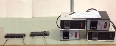
Figure 5.8: Dummy specimens with attached thermocouples determine the temperature of the specimens inside the chamber
2. Fatigued Specimens
An additional set of 18 specimens was fatigue loaded under constant cycles, up to a maximum load of 20 % of the specimen’s ultimate strength which (that was independently determined). Nine of these specimens had been pre-exposed at the three different temperatures (20, 40, 50 0C), while the other nine were directly tested under fatigue load (i.e., without pre-exposure). Under each condition, triplicate tests were performed, in order to estimate the scatter in the data. Fatigue testing was performed using an MTS Instron machine with load cell capacity of 100 kN. All tests were performed at a frequency of 10 Hz and a stress ratio of 0.1. The tests were terminated after 2 million cycles and the specimens then subjected to static load until failure. This was done in order to determine the effect of fatigue load on the ultimate strength of the bond. The results of these tests are shown in Table 2.
5.4.4 Results and Discussion
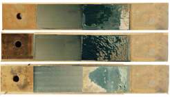
The average ultimate tensile strengths for the specimens and the coefficients of variation with and without pre-exposure to the environment for two weeks are shown in Table 5.2. Here we see that the failure load decreased as temperature increased. On the other hand, pre-exposure procedure has no significant effect on the failure load see Figure 5.9. Figure 5.10 shows that the specimens exhibited both cohesive and adhesive failure at all temperatures [7, 11, 22]. Unfortunately, this means that the surface preparation was inappropriate. This study led to the realisation that alternative surface preparations were needed.
Table 5.2 Average ultimate loads (Fult) and coefficient of variation of CFRP laminate repaired steel plates at different temperatures with and without pre-exposure to environment
|
Temperature (oC) |
Average value of Ultimate loads Fult (kN) |
Coefficient of variation |
|
|
Ultimate strength (kN) (Fave) without pre-exposure |
20 40 50 |
89 56 44 |
0.01 0.05 0.07 |
|
Ultimate strength (kN) after immersion for 2 weeks (Fave) |
20 30 50 |
78 50 40 |
0.02 0.06 0.07 |

Figure 5.9 Static strength of CFRP laminate/steel bonded specimens
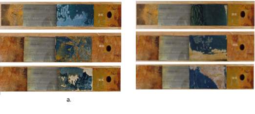
Figure 10 Optical images of control specimens after failure, a) with pre-exposure b) without pre-exposure to environment
Bai (2013) [10] reported the effect of varying temperature on tensile strength, whereas, Borrie (2015) [11] tested samples after pre-exposure to environment at different temperatures. In the present study, tests were conducted under the simultaneous effect of environment, load, and with and without pre-exposure. The dimensions and the materials were chosen to be the same as those in [10, 11] for the purpose of comparing the results. Among the various test conditions, simultaneous exposure of pre-exposure samples to environment at an elevate temperature conditions the most severe condition that deteriorates the ultimate strength most drastically. The three various studies is presented in Figure 5.11. The raw data for all specimens can be found in Table A1 (in appendix A).
Figure 5.11 The bond ultimate strength FULT(kN) of CFRP repaired steel obtained under four different procedures of exposure to the environment.
Figure 5.10 reveals that the failure modes involved both cohesive and adhesive failure, which is similar to the failure of the specimens tested under the combined effect of environment and fatigue load see Figure 5.12. This suggests that the bonding process recommended in [7, 11, 19, and 20] is not optimal. Thus, a conclusion will be examined in more details in Chapter 6.

200C
200C
400C 0jjhk0CC00C
500C 0jjhk0CC00C
500C 0jjhk0CC00C
(b)
(a)
Figure 5.12 Optical images of fatigued specimens after failure, a) with pre-exposure b) without pre-exposure to environment
5.5 A Mean for Evaluating Bond Quality Prior to Testing
The results described in the previous section revealed that means for quantifying the bond prior to testing is essential. This has been a shortcoming in several previous studies [21]. Unfortunately, “kissing bonds” and poor bond can’t be determined via standard NDI tests. To meet this challenge, Lockin-thermography, which uses Kelvin’s law to link the infra-red emission to the surface stress field, this has been widely used to study composite repairs and fatigue life extension process [15].
In this context, researchers have shown that corrosion can be detected using Lock-in infrared thermography in steel and galvanized steel panels that were coated with an organic paint. Aerospace researches have been also shown that material disbond can be easily detected using this system. Lock-in thermography involves heating the structure using a sinusoidal input of heat energy at a frequency ω, produces both amplitude and phase difference images both at the (1st harmonic) ω and also other harmonics the most relevant of which (to this study) is the 2nd harmonic 2ω. The amplitude image represents the amplitude (peak-to-peak) thermal response of the structure. The phase image is generated by phase difference measured between the input and the measured signal. The phase image is often more useful than the amplitude image for detecting subsurface defects.
In this part, Lock-in infrared thermography has been used to monitor the disbanding in the interface between CFRP and steel in DOF specimen.
To evaluate the potential of this procedure, the CFRP repairs to steel specimen was fatigue cycled, (see Figure 5.13). Figure 5.14 shows the resultant stress field. Here the dislocation in the stress field at the edges located over the joint are indicated. Such disbonds will induce adhesive failure in an aggressive environment. This test substantiates the conclusion reached in the previous experiment that the process used to bond the specimens need to be improved.
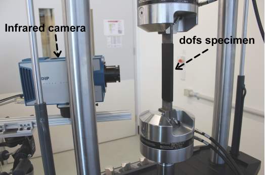
Figure 5.13: Photograph of the dofs under test
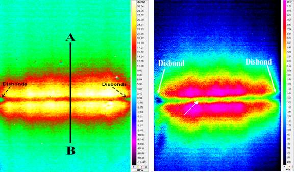
Side A Side B
Figure 5.14 Stresses on the surface of the patch of two sides (upper adherend)
5.6 Designing CFRP repairs, the classical lap joint theory testing
The CMH-17-3G Composites Material Handbook [1] documents the formulae used to design bonded joints. These formulae which were validated as part of the USAF Primary Adhesively Bonded Structure (PABST) program [2], were originally developed by Dr. John Hart-Smith [3, 4]. In This formulation, it is assumed that the stresses are constant through the inner (steel) and outer (CFRP) adherends. It predicts that for a dof specimen the peak stress in the adherend occurs directly over the joint. Figure 15 reveals, that part of the PABST (Hart-Smith [15-17]) analysis is incorrect since the peak stresses actually occur slightly to each side of the joint. This feature is due to the complex 3D nature of the stress field in the dof specimen [24].
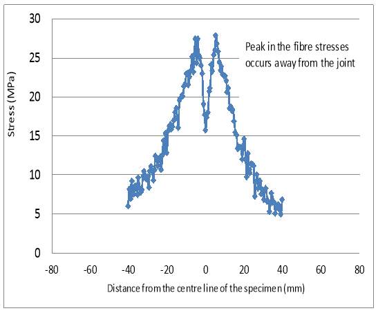 Figure 5.15 Stresses along line AB in the centre of the patch (shown in Figure 14)

 The next stage in this study was analysing the stresses along the joint of dof specimen using the finite element model (FEMAP & NASTRAN software) see Figures 5.16 and 5.17.
Figure 5.16 The configuration of the half of the dof specimen using FEMAP and Nastran software
|
|
|


Figure 5.17 The analysing the DOFS using FEMAP and Nastran software

Figure 5.18: Stress at Top Surface, half of the specimen
It is clear from the predicted stresses along the surface of the joint which resulted from using the finite element model (see figure 18), that the stress distribution have a camel hump configuration, which means that the peak of the stresses lies on either sides of the joint and not over the joint directly. This means that the FEMAP models clearly simulated the stress configuration and the results were in satisfactory agreement with the experimental results.
5.7 Conclusions
From the investigations reported in this chapter, following conclusions can be drawn:
2) By comparing the results with those presented by Borrie [11] and shown in Fig.5.11, it is clear that pre-exposure followed by an aggressive environment significantly reduces the residual strength of the bond;
3) The failure modes involved a combination of cohesive and adhesive failure;
4) Inspection of the bond quality reveals the presence of disbond as the adhesive touching but not bonding). Therefore, an alternative bonding process is required to get better bonding;
5) It is clear that effective bonding process that can withstand combined fatigue-environment is required. Chapter six will examine the Boeing-USAF surface preparation procedures viz: the use of grit blast and sol gel;
6) It has been proved experimentally and analytically that the peak of the stress in the double overlap fatigue specimen (dof specimen) lies on either sides of the joint and not exactly over the joint, and this finding is important since it contradicts the PABST formula which stated that the peak lies directly over the joint.
- CMH-17-3G, Composite Materials Handbook, Volume 3: Polymer Matrix Composites Materials Useage, Design and Analysis, Published by SAE International, March 2012.
- Potter DL., Primary adhesively bonde d structure technology (PABST): Design handbook for adhesive bonding, USAF Technical Report, AFFDL-TR-79-3129, November 1979.
- Jafari S., Singh R., Corrosion fatigue behaviour of a common AZ91D magnesium alloy in modified simulated body fluid, Advanced Materials Research, (2014), Volume 891, Issue 5, pages 267-272.
- Liu, H.,Zhao XL., and Al-Mahaidi R., Effect of fatigue loading on bond strength between CFRP sheets and steel plates. International Journal of Structural Stability and Dynamics, 2010. 10(01): p. 1-20.
- J. Crank and G.S. Park, Diffusion in polymers, Book, London; New York, N.Y., Academic Press, 1968.
- Al-Harthi M, Loughlin K, Kahraman R. Moisture diffusion into epoxy adhesive: testing and modeling. Adsorption 2007;13: 115–20.
- Nguyen T, Bai Y., Zhao XL., and Al-Mahaidi R., Durability of steel/CFRP double strap joints exposed to sea water, cyclic temperature and humidity. Composite Structures, 2012b. 94(5): p. 1834-1845.
- Baker A. and Jones R., Bonded Repair of Aircraft Structure. 1988, The Hague: Martinus Nijhoff Publishers. pp 107- 173.
- Baker A. A. (2002) Introduction and overview. In: Advances in the Bonded Composite Repair of Metallic Aircraft Structure. Elsevier, p. 1-18.
- Bai Y Nguyen TC, Zhao X-L, Al-Mahaidi R. Environment-assisted degradation of the bond between steel and carbon-fiber-reinforced polymer. J Mater Civ 2014; 26(9):1–8.
- Borrie D, Liu H., Zhao XL., Singh R, Bai Y., Bond durability of fatigued CFRP-steel double-lap joints pre-exposed to marine environment. Composite Structures, 2015. 131: p. 799-809.
- Matta F. (2003) Bond between steel and CFRP laminates for rehabilitation of metallic bridges, Ph.D Thesis, University of Padua, Padua.
- Zhao, X.-L., et al., Effect of dynamic loading and environmental conditions on the bond between CFRP and steel: state-of-the-art review. Journal of Composites for Construction, 2013. 18(3).
- Fawzia, S. and M.H. Kabir. A review on environmental durability of CFRP strengthened system. In Australasian Structural Engineering Conference 2012: The past, present and future of Structural Engineering. 2012. Engineers Australia.
- Hart-Smith, L.J., Adhesively bonded double lap joints, NASA CR 112235, January 1973.
- Thrall EW., Primary adhesively bonded structure technology (PABST): Design handbook for adhesive bonding, USAF Technical Report, AFFDL-TR-79-3119, 1979.
- L. J. Hart-Smith, “Further Developments in the Design and Analysis of Adhesive-Bonded Structural Joints”, Douglas Aircraft Company Paper 6992,
- presented to ASTM Symposium on Joining of Composite Materials, Minneapolis, Minnesota, April 1980; published in ASTM STP 749.
- M. Tavakkolizadeh and H. Saadatmanesh, “Fatigue strength of steel girders strengthened with carbon fiber reinforced polymer patch,” Journal of Structural Engineering, vol. 129, no. 2, pp. 186–196, 2003.
- J. Teng, D. Fernando, T. Yu, and X. Zhao, “Treatment of steel surfaces for effective adhesive bonding,” in Advances in FRP Composites in Civil Engineering, pp. 865–868, 2011.
- D. Schnerch, M. Dawood, S. Rizkalla, E. Sumner, and K. Stanford, “Bond behavior of CFRP strengthened steel structures,” Advances in Structural Engineering, vol. 9, no. 6, pp. 805–817, 2006.
- Ahmed Al-Shawaf, Xiao-Ling Zhao, Adhesive rheology impact on wet lay-up CFRP/steel joints’ behaviour under infrastructural subzero exposures, Composites: Part B 47 (2013) 207–219.
- X. HAN1,2, A. D. CROCOMBE1 , S. N. R. ANWAR1,3, P. HU2 , and W. D. LI2, “The Effect of a Hot–Wet Environment on Adhesively Bonded Joints Under a Sustained Load”, The Journal of Adhesion, 90:420–436, 2014.
- Jones, R. and Paul, J., Aeronautical Research Laboratories, Australia, Structures Report 402 (1984).
- Miller T. C., Chajes M. J., Mertz D. R. and Hastings J. N. (2001) Strengthening of a Steel Bridge Girder Using CFRP Plates. Journal of Bridge Engineering, ASCE, 6(6):514-522. (1)
- Hollaway L. C. and Cadei J. (2002) Progress in the technique of upgrading metallic structures with advanced polymer composites. Progress in Structural Engineering and Materials, 4(2):131-148.
- Liu H. B., Xiao Z. G., Zhao X. L. and Al-mahaidi R. (2008) Prediction of fatigue life for CFRP strengthened steel plates. Thin-walled Structures (Accepted for Publication).
- Liu H. B., Zhao X. L. and Al-Mahaidi R. (2005a) The effect of fatigue loading on bonding strength of CFRP bonded steel plate joints. In: Proceedings of the International Symposium on Bond Behaviour of FRP in Structures, Hong Kong, China, p. 459-464.
- Karbhari V. M., Chin J. W., Hunston D., Benmokrane B., Juska T., Morgan R., Lesko J. J., Sorathia U. and Reynaud D. (2003) Durability gap analysis for fibre-reinforced polymer composites in civil infrastructure. Journal of Composites for Construction, ASCE, 7(3):238-247.
|
Static Tensile Test of CFRP Laminate Repairs Steel |
Temperature (oC) |
Ultimate Strength F1ult (kN) |
Ultimate Strength After fatigue F2ult (kN) |
Ultimate Strength (kN) (F1ave) |
Ultimate Strength (kN) (F2ave) after fatigue |
Stress Ratio (F2ave /F1ave) |
||||
|
Spe1 |
Spe 2 |
Spe 3 |
Spe.1 |
Spe 2 |
Spe 3 |
|||||
|
Direct Test under The Simultaneous Effect of Environment + Load |
20 |
88 |
89.5 |
90 |
85 |
84 |
85 |
89 |
84 |
0.94 |
|
40 |
58 |
55 |
54 |
55 |
50 |
49 |
56 |
51 |
0.92 |
|
|
50 |
39 |
49 |
45 |
45 |
40 |
39 |
44 |
41 |
0.94 |
|
|
Immersed the Specimens for 2 Weeks Before the Test |
20 |
77.5 |
76 |
80 |
73 |
72 |
66 |
78 |
70 |
0.9 |
|
40 |
56 |
51 |
44 |
42 |
44 |
45 |
50 |
44 |
0.88 |
|
|
50 |
33 |
47 |
37 |
31 |
Failed |
33 |
40 |
32 |
0.8 |
|
APPENDIX A – RAW DATA FROM BOND DURABILITY EXPERIMENTS (SECTION 5.2)
Cite This Work
To export a reference to this article please select a referencing stye below:
Related Services
View all


DMCA / Removal Request
If you are the original writer of this essay and no longer wish to have your work published on UKEssays.com then please click the following link to email our support team:
Request essay removal