Gain Enhancement of Multiband Microstrip Radiating Structure
| ✅ Paper Type: Free Essay | ✅ Subject: Engineering |
| ✅ Wordcount: 2622 words | ✅ Published: 24 Nov 2017 |
Gain Enhancement of Multiband Microstrip Radiating Structure using Curve Tooth CSRR with Two Different Substrate Material
- Muktesh P. Shah1, Shobhit K. Patel2, Mayank A. Ardeshana3, Jigar M. Patel4
Abstract—In this paper Microstrip radiating structure with Complementary Split Ring Resonator (CSRR) using Curve Tooth with two different substrate material for Multiband applications in S band and C band is designed and analyzed. We have introduced Curve Tooth in CSRR to improve Gain in comparison with simple CSRR based design. Also, The same design with two different substrate material like FR4 and Teflon is compared and analyzed. Here, Patch of dimension 44×44mm2 is analyzed. The FR4 based design of Curve Tooth in CSRR has five working bands centered around 1580 MHz, 3180 MHz, 3600 MHz, 4580 MHz, 7190 MHz and Simple CSRR Design has three working bands with center frequency 1560 MHz, 3150 MHz and 3540MHz. The Teflon based design of Curve Tooth in CSRR has five working bands centered around 2250 MHz, 4560 MHz, 5150 MHz, 6540 MHz, 8310 MHz and Simple CSRR Design has four working bands with center frequency 2213 MHz, 4508 MHz, 5050MHz and 6395 MHz. Design results of VSWR, Return loss S11 and Total Gain of all four design is shown and compared in this paper. Also, Design results shows improvement in Gain in Curve Tooth CSRR design. The dimensions of substrate height is 1.57 mm, Patch and Ground height is 0.035 mm which are similar to actual Antenna dimensions. Design results are obtained by a HFSS 13 (High Frequency Structure Simulator) which is mostly used for simulating microwave passive components.
Index Terms— Curve Tooth, CSRR (Complementary Split Ring Resonator), Substrate Materials, Multiband, Microstrip.
I. Introduction
Nowadays, Multiband antenna is a popular choice because same antenna can be used for many applications [12][15][17][18][19]. Microstrip patch antennas are widely used because of their many merits, such as the low volume, light weight, low cost etc. [1-8] However, Patch antennas have a main disadvantage: narrow bandwidth while others are low gain, low power handling capacity etc. [1-8] Still there is a need to design Multiband antenna with improvement in Gain. Metamaterial may solve this need.
In Recent Scenario, Microstrip patch antennas are widely used in wireless devices and other compact sizes with multiband antenna operation. The irregular shape of the developed planar antenna achieves multi-band (Broadband) performance [11]. In traditional planar antennas, the distances between the edges are fixed and therefore, the antennas dominant mode resonates only at a single frequency [11]. In contrast, the irregular shape of the current antenna facilitates, its broadband character by allowing the structure to have more than one degenerate mode that resonate at more than one frequency, based on the irregularity introduced [11]. In general, multi-sided patches are excellent candidates for broadband operation, since many closely spaced resonant modes can be excited using the different edges of the patches [11]. This property makes them uniquely suited for multi-band operation in wireless applications.

There has been a considerable amount of recent interest in the class of artificial material which is known as Metamaterials that possess simultaneously negative permeability and permittivity, according to a negative index of refraction [1][2]. Such type of metamaterial is known as a double negative material (DNG). To increase the power radiated from electrically small antennas, an application of DNGs has been suggested by Ziolkowski and Kipple [3]. But in this paper a negative permittivity material complementary split ring resonator (CSRR) which is a dual counterpart of split ring resonator (SRR) originally proposed by Pendry have been loaded into the patch. CSRR is composed of two concentric metallic ring slots with slits etched in each ring at its opposite sides. Apart from double negative materials, single negative materials where only one of the material parameters has a negative real value also possess interesting properties and can be used to produce novel devices. In particular the complementary split ring resonator (CSRR) which establishes a negative-permittivity at resonance, is an example of a single negative media (SNG) that can be used to make microwave devices [4]-[6]. Here, we have incorporated curve tooth CSRR to further improve the results of CSRR. The properties of SNG can also be manipulated to increase filter shape factor, improve filter rejection and can also applied to antennas to reduce the spurious effect and increase antenna gain and antenna size reduction [7][9][16][17]. This paper is based on the microstrip radiating structure which integrates a Curve Tooth CSRR design into the ground to provide good return loss and improved gain.
The CSRR is a commonly used resonator etched on the
Metal plane. An effective negative permittivity and negative permeability could be introduced in microstrip devices by loading CSRR [17][18]. In this article, we have etched the CSRR in the ground plane of a microstrip patch underneath the substrate. The CSRR structure model is shown in Figure 1. If the effects of the metal thickness and losses, as well as those of the dielectric substrate are ignored, a perfectly dual behavior is expected for the complementary screen of the SRR. Thus, whereas the SRR can be mainly considered as a resonant magnetic dipole that can be excited by an axial magnetic field, the CSRR (Fig. 1) in essence behaves as an electric dipole (with the same frequency of resonance) that can be excited by an axial electric field. Fig. 1 shows the unit cell structure of SRR model and CSRR model with its equivalent electrical circuit.

Fig. 1 (a) SRR unit cell, (b) Equivalent electric circuit of SRR unit cell, (c) CSRR unit cell, and (d) equivalent electric circuit of CSRR unit cell. [15]
II. Design and Simulation
In this section, we will introduce the design of our antenna. First the conventional patch length and width is designed. After designing the patch, we have taken out five slots from the patch to improve the radiation path. Basic length and width is designed with the use of following equations [5].

Width of the patch can be designed using the equation (1), here f0 is the resonance frequency, εr is relative permittivity of the dielectric substrate and c is speed of light.


Length of the patch can be designed by using the equations (2-5) [5]. Here‘t’ is the thickness of substrate. Using these equations we have derived length and width of conventional patch.
We designed square patch so length and width are same and it is 44 mm, so a square patch is 44×44 mm2 over here which is shown in Figure 2 (a). We have taken out five slots from the patch to increase the Radiation path and to improve the results as shown in figure. The slots taken out have dimension of 8×8 mm2.
A. Design 1
The top view of the Simple CSRR design and Curve tooth with CSRR Design is shown in Figure 2 (a) and 2 (b) respectively. Both the design has outer and inner ring is of 1 mm. Gap between the two rings is 1.5 mm.
Table: 1 Material used for Design1
|
Design 1 |
Material |
|
Patch |
Copper |
|
Substrate |
Teflon with ε = 2.1 |
Table 1 shows details about the material. Patch is of copper material. Substrate is of Teflon material with ε = 2.1. The base material is also of copper.
 Fig. 2 (a) HFSS Model of Simple CSRR Design

Fig.2 (b) HFSS Model of Curve Tooth CSRR Design
For simulation we used HFSS 13 (High Frequency Structure Simulator) of Ansoft, which is very good simulator for simulating microwave passive components specially RF antenna.
 Figure 3 (a) and 3 (b) shows the Return Loss (S11) in dB for both the designs. The minimum return loss which we are getting for Simple CSRR design is -31 dB for the band centered around 4.508 GHz and for Curve Tooth CSRR design, it is -37 dB for the band centered around 4.56 GHz.
Figure 4 (a) and 4 (b) shows the VSWR plot for both the designs.

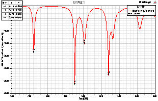
Fig. 3 (a) Return Loss (S11) plot of Simple CSRR Design


Fig. 3 (b) Return Loss (S11) plot of Curve Tooth CSRR Design

Fig. 4 (a) VSWR plot of Simple CSRR Design
 Fig. 4 (b) VSWR plot of Curve Tooth CSRR Design
B. Design 2
Here, We have used same design but only substrate material is changed. In this Design we have used FR4 epoxy material for substrate.
Table: 2 Material used for Design1
|
Design 1 |
Material |
|
Patch |
Copper |
|
Substrate |
FR4 epoxy with ε=4.4 |


Fig. 5 (a) Return Loss (S11) plot of Simple CSRR Design


Fig. 5 (b) Return Loss (S11) plot of Curve Tooth CSRR Design

Fig. 6 (a) VSWR plot of Simple CSRR Design


Fig. 6 (b) VSWR plot of Curve Tooth CSRR Design
Figure 5(a) and 5(b) shows Return loss plot of both CSRR and Curve Tooth CSRR design. Figure 6(a) and 6(b) shows VSWR plot for both the design.
III. Comparative Analysis
A. Design 1
In this design, we used Teflon as a substrate material in which Curve Tooth design has five working bands while Simple CSRR design has four working bands.
Table 3 shows comparison of Return loss and VSWR of the both the design.
Table 3 : Comparison of S11 and VSWR for both design
|
Band |
Design |
Frequency in GHz |
Minimum Return Loss (S11) in dB |
VSWR |
|
First |
CSRR |
2.213 |
-18.8 |
1.2601 |
|
Curve tooth CSRR |
2.25 |
-17 |
1.331 |
|
|
Second |
CSRR |
4.508 |
-31 |
1.0549 |
|
Curve tooth CSRR |
4.56 |
-37.6 |
1.0268 |
|
|
Third |
CSRR |
5.05 |
-15 |
1.4183 |
|
Curve tooth CSRR |
5.15 |
-14.8 |
1.4434 |
|
|
Fourth |
CSRR |
6.395 |
-27.7 |
1.0862 |
|
Curve tooth CSRR |
6.54 |
-24.7 |
1.1243 |
|
|
Fifth |
CSRR |
—– |
—– |
—– |
|
Curve tooth CSRR |
8.31 |
-12 |
1.6624 |
By using curve tooth in CSRR, we have an extra working band and also return loss and VSWR values are very good. We got VSWR of 1.0268 using curve tooth which is nearer to 1.
Figure 7(a) and 7(b) shows Total Gain plot in 3D view for CSRR and Curve tooth CSRR design respectively.


Fig.7 (a) Total Gain plot in 3D view for simple CSRR design

Fig.7 (b) Total Gain plot in 3D view for Curve Tooth CSRR design
Simple CSRR design has Total Gain of 2.6609 dB while Curve Tooth CSRR design has Total Gain of 2.9264dB. So using Curve tooth in CSRR we have improved gain.
B. Design 2
In this design, we used FR4 epoxy as a substrate material in which Curve Tooth design has five working bands while Simple CSRR design has four working bands.
Table 3 shows comparison of Return loss and VSWR of the both the design.
By using curve tooth in CSRR, we have two extra working bands and also return loss and VSWR values are very good. We got VSWR of 1.0931 using curve tooth which is nearer to 1. Figure 8(a) and 8(b) shows Total Gain plot in 3D view for CSRR and Curve tooth CSRR design respectively.
Simple CSRR design has Total Gain of -0.2895 dB while Curve Tooth CSRR design has Total Gain of 3.0368dB. So using Curve tooth in CSRR we have sufficiently increased the gain.
|
Band |
Design |
Frequency in GHz |
Minimum Return Loss (S11) in dB |
VSWR |
|
First |
CSRR |
1.56 |
-23.6 |
1.1407 |
|
Curve tooth CSRR |
1.58 |
-27 |
1.0931 |
|
|
Second |
CSRR |
3.15 |
-18 |
1.2780 |
|
Curve tooth CSRR |
3.18 |
-19 |
1.2429 |
|
|
Third |
CSRR |
3.54 |
-25 |
1.1197 |
|
Curve tooth CSRR |
3.60 |
-24 |
1.1318 |
|
|
Fourth |
CSRR |
—– |
—– |
—– |
|
Curve tooth CSRR |
4.58 |
-13.9 |
1.5070 |
|
|
Fifth |
CSRR |
—– |
—– |
—– |
|
Curve tooth CSRR |
7.19 |
-17 |
1.3172 |
Table 4 : Comparison of S11 and VSWR for both design


Fig.8 (a) Total Gain plot in 3D view for simple CSRR design


Fig.8 (b) Total Gain plot in 3D view for Curve Tooth CSRR design
IV. Conclusion
Here Microstrip patch antenna is designed for multiband applications using five rectangular square slots in the Patch and CSRR in ground. Curve Tooth is also implemented in CSRR to improve the results. Two designs with different substrate material is designed and analyzed. This antenna is compared with simple CSRR design. The result of Design 1 which has Teflon substrate, indicates the five working bands for Curve Tooth CSRR design, 2.25 GHz, 4.56 GHz, 5.15 GHz, 6.54 GHz and 8.31 GHz so the antenna can used for S and C Band Applications while Simple CSRR has four working bands. VSWR is very good for 4.56 GHz frequency which is 1.0268 near to 1. Also, Gain has been improved with Curve Tooth CSRR which is 2.9264 dB compare to Simple CSRR design which has gain of 2.6609 dB. Design 2 which has FR4 substrate, provides five working bands for Curve Tooth CSRR while CSRR design has three working bands. Also, Gain for Curve Tooth CSRR has 3.0368 dB compare to -0.2895 dB for simple CSRR design. So, by using Curve Tooth in CSRR improves results. Also, Dimensions of all Designs are similar to Actual Antenna so when we fabricate the antenna, we will get similar results.
References
- V.G. Vesalago, “The Electrodynamics of Substances with Simultaneously Negative Values of Permittivity and Permeability”, Sov. Phys. USPEKHI, pp. 509-514, 1968.
- D.R. Smith, W.J. Padilla, D.C. Vier, S.C. Nemat-Nasser, and S. Schultz, “Composite Medium with Simultaneously Negative Permeability and Permittivity”, Phys. Rev. Lett., 84, No. 10, pp. 4184-4187, 2000.
- R.W. Ziolkowski and A.D. Kipple, “Application of Double Negative Materials to Increase the Power Radiated by Electrically Small Antennas”, IEEE Transactions on Antennas and Propagation, 51, No. 10, pp. 2626-2640, October 2003.
- F. Falcone, T. Lopetegi, J.D. Baena, R. Marques, F. Martin, and M. Sorolla, “Negative- E Stop-Band Microstrip Lines Based on Complementary Split-Ring Resonators”, IEEE Microw. Wireless Compon. Lett, 14, No. 6, pp. 280-282, Jun. 2004.
- J. D. Baena, J. Bonache, F. Martin, R. Marques, F. Falcone, et.al., “Equivalent-Circuit Models for Split Ring Resonators Coupled to Planar Transmission Lines, “IEEE Trans. Microw. Theory Tech, 53, No. 4, pp. 1451-1461, Apr. 2005.
- J. Garcia-Garcia, , F. Martin, F. Falcone, J. Bonache, J.D. Beano, et.al, “Microwave Filters with Improved Stop Band Based on Sub Wavelength Resonators” IEEE Trans. Microw. Theory Tech, 53, No. 6, pp. 1997-2006, June. 2005.
- J.J. Max, Y. Cao and T. Liu, “Design the Size Reduction Patch Antenna Based on Complementary Split Ring Resonator, “ICMMT 2010 proceedings.
- Hui Zhang, You-Quan Li, Xi Chen, Yun-Qi Fu, and Nai-Chang Yuan, “ Design of Circular Polarization Microstrip Patch Antenna using Complementary Split Ring Resonator”, 978-1-4244-2609-6, IEEE 2008.
- D. Laila, R. Sujith, V. Deepu, C.K., Vasudevan Aanandan and P. Mohanan, “Compact Csrr Based Patch Antenna for Wireless Applications”, 978-1-4244-4819-7, IEEE 2009.
- N. Ortiz, F. Falcone, M. Sorolla, “Dual Band Patch Antenna Based on Complementary Split Ring Resonator”, 978-1-4244-2802-1, IEEE 2009.
- Zygmond Turski, Aly E. Fathy, David McGee, Gary Ayers, and Sridhar Kanamaluru, “Compact Multi-Band Planar Antenna for Mobile Wireless Terminals,” IEEE, 2001.
- M.P.Shah, S. K. Patel, M.A.Ardeshana, J.M. Patel, “Design of Multiband microstrip Radiating Structure for C band Applications,” IJARCCE, Vol.2, Issue.12, Dec 2013, pp. 4560-4563.
- S. K. Patel, J. Bhalani, Y.P. Kosta, S.S. Patel, “Design of microstrip meandered patch antenna for mobile communication,” Proceedings of International conference on Advances in Information Technology and Mobile Communication (AIM 2011), Springer, 2011, pp. 184–189.
- S.K. Patel and Y.P. Kosta, “E-shape microstrip patch antenna design for GPS application,” Proceeding of Nirma University International conference on Engineering (NUiCONE 2011). IEEE, 2011, p. 1-4.
- S.K. Patel and Y.P. Kosta, “Meandered multiband metamaterial square microstrip patch antenna design,” Waves in Random and Complex Media, in press, 2012(DOI: 10.1080/ 17455030.2012.723837).
- S.K. Patel and Y.P. Kosta, “Size reduction in Microstrip based radiating structure with artificial substrate,” International Journal of Applied Electromagnetics and Mechanics, in press, 2012.
- S.K. Patel and Y P Kosta, “Investigation on radiation improvement of corner truncated triband square microstrip patch antenna with double negative material,” Journal of Electromagnetic Waves and Applications, 2013, Vol. 27, No. 7, 819–833.
- S.K. Patel and Y P Kosta, “Triband microstrip–based radiating structure design using Split ring resonator and complementary split ring resonator,” Microwave And Optical Technology Letters / Vol. 55, No. 9, September 2013, Wiley periodicals.
- J. M. Patel, S. K. Patel and F. N. Thakkar, “Defected Ground Structure Multiband Microstrip Patch Antenna using Complementary Split Ring Resonator,” IJETEE, Vol. 3, Issue. 2, May 2013.
- S.K. Patel and Y.P. Kosta, “Design of Truncated microstrip radiating structure loaded by SRR,” International Journal of Applied Electromagnetics and Mechanics, in press, 2012.
- S.K. Patel and Y.P. Kosta, “Dual band parasitic metamaterial square microstrip patch antenna design,” International Journal of Ultra Wideband Communications & Systems 2, no. 4, pp. 225-232 2012.
- J. M. Patel, S. K. Patel and F. N. Thakkar, “Comparative analysis of S-shaped Multiband Microstrip patch antenna,” IJAREEIE, Vol. 2, Issue. 7, July 2013.
- J. M. Patel, S. K. Patel and F. N. Thakkar, “Design of S-shaped Multiband microstrip patch antenna,” NUiCONE, IEEE, 2012.
Cite This Work
To export a reference to this article please select a referencing stye below:
Related Services
View all


DMCA / Removal Request
If you are the original writer of this essay and no longer wish to have your work published on UKEssays.com then please click the following link to email our support team:
Request essay removal