Implementation of Reliable and Cost Effective Smart Home
| ✅ Paper Type: Free Essay | ✅ Subject: Engineering |
| ✅ Wordcount: 3019 words | ✅ Published: 31 Aug 2017 |
Automation is the trend that will define the way we will live and work over the next decade. Current home automation systems have limitations in terms of wireless connectivity, speed, interference, bandwidth and cost of implementation. The proposed smart home system provides wireless control of appliances such as lights, fans, and alarms by using sensors and Bluetooth. Bluetooth provides higher transmission speed, greater bandwidth, and consumes less power than existing wireless protocols. Further, the cost of implementation is minimized with the use of sensors and Bluetooth. This design incorporates an ARM7 processor that continuously collects light intensity, temperature, and carbon-monoxide levels from sensors and compares it with threshold levels, to determine the control operation to be performed on home appliances. The ARM7 processor access appliances using Bluetooth. Further, this smart home system also allows individuals to directly control their appliances through a smartphone-based android application. This smart home system is implemented and tested under varying conditions to represent its efficiency.
LIST OF ABBREVIATIONS
|
ADC |
Analog to Digital Converter |
|
ARM |
Advanced RISC Machines |
|
BLE |
Bluetooth Low Energy |
|
CPSR |
Current Program Status Register |
|
DTE |
Data Terminal Equipment |
|
FEC |
Forward Error Correction |
|
FH-CDMA |
Frequency Hopping Code Division Multiple Access |
|
FIQ |
Fast Interrupt Request |
|
HVAC |
High Voltage Alternating Current |
|
LCD |
Liquid Crystal Display |
|
PPM RISC |
Parts Per Million Reduced Instruction Set Computer |
|
RSSI |
Received Signal Strength Indicator |
|
UART |
Universal Asynchronous Receiver/Transmitter |
|
UPB |
Universal Powerline Bus |
|
USB |
Universal Serial Bus |
CHAPTER 1
INTRODUCTION
Home Automation
World’s Fair of 1934 in Chicago marked the birth of home automation. Initially, the industry could not make an enormous impact on society. The reason for the slow start was high price and complexity making it hard to install. However as smartphones and tablets came into existence, the implementation of this technology became much easier. The automation technology helps in achieving greater efficiency and provides higher security.
Expectations from a Smart Home
The major parameters to look for in the implementation of a smart home can be as follows:
Compatibility of the protocol. The system should communicate with the major protocols in home automation like ZigBee, Z-Wave, and Bluetooth.
Wireless access. The system should be capable of wireless connection such as Wi-Fi Connectivity thereby eliminating all physical complexities.
Scope for expansion. The system should support a higher number of products.
Scope for scheduling. The design of the system should be able to support scheduling of different tasks at home like turning off lights when nobody at home.
Remote access. Having an Android support is imperative these days. If the system is compatible with a smartphone, it makes this process very smooth as almost every individual today has a smartphone.
Emergency notification. The system should send messages indicating emergency or threat to the house.
Smart Home – Community Response
Various studies have been conducted to find out if consumers are ready to take up smart home technology. A study from Coldwell Banker Real Estate and CNET carried out in June 2015, said that 28% of internet users in The United States have smart homes and 90% of them would recommend smart home technology. The report also suggests that 25% of Americans use smart home products which save them around 30 minutes a day on average which are equivalent to $1,000 per year. As per a survey, 75% of the smart homeowners believe that this technology brings peace of mind regarding security.
CHAPTER 2
REVIEW OF LITERATURE
Existing Protocols in Home Automation Industry
The increase in the use of smart home systems leads to the development of different protocols. The protocols are selected based on the type of communication among various connected devices. Let us see the major protocols in home automation industry:
X10 Technology
X10 is the oldest home automation protocol developed in 1970. Initially, the technology was a powerline-based system which slowly went wireless. X10 technology uses the power lines in the home to allow communication between various appliances. X10 is reliable as it makes use of power lines. However, it is subject to interference from other devices in the circuit. It does not provide a speed communication between devices. It can only perform 16 commands sent one at a time.
INSTEON Technology
INSTEON was introduced in the year 2005. It was designed to bridge the gap between powerline systems and wireless protocols. INSTEON is compatible with X10 technology making it easy for those who have an existing X10 network. It supports automation novices which make setting up or adding devices easy for the non-technical users. INSTEON can support more than 65,000 commands.
It is capable of transmitting commands with little interference. One need not have to enroll INSTEON into home automation network. INSTEON network can have more than 400 devices connected in a single installation. The dual-band mesh network can convert all powerline-operated devices into repeaters
ZigBee Technology
ZigBee is a wireless communication standard built by IEEE. It runs on 802.15.4 wireless communication standard. ZigBee is growing significantly in recent times. However, ZigBee’s full acceptance as a home automation protocol is still in question. The reason being its interoperability. In most cases, ZigBee devices have difficulty in communicating with devices from other manufacturers. Each device uses different methods to accomplish the same task which causes the difficulty in communication. Perhaps, for the same reason, manufacturers use ZigBee to limit third-party devices.

Wi-Fi Technology
Wi-Fi stands for Wireless Fidelity. Wi-Fi makes use of radio frequency transmission of data through the air. Speed in a Wi-Fi connection may vary from 1mbps to 2mbps. Wi-Fi works in the frequency band of 2.4 GHz. The range for Wi-Fi is 40-300 feet. Wi-Fi runs on an inbuilt technology known as frequency division multiplexing technology.
However, the major drawback with Wi-Fi is the interference and bandwidth issues. With too many Wi-Fi compatible devices, each device must fight for bandwidth resulting in more time to respond thereby making it work slowly. Also, Wi-Fi consumes much power.
CHAPTER 3
BLUETOOTH TECHNOLOGY
In 1994, Ericsson Mobile Communications was the first to initiate research on the possibility of wireless links. Their aim was to develop a cost-effective solution to replace cables as a mode of communication between computers and peripherals. Ericsson along with Nokia, Intel, IBM, and Toshiba, formed a group known as Bluetooth Special Interest Group (SIG) with a common motive of developing the unique technology. The first Bluetooth technical specification released in 1999.
Bluetooth Specification
Bluetooth specification for Classic Bluetooth/Bluetooth Basic Rate/Enhanced Data Rate (BR/EDR) is below in Table 1.
TABLE 1. Specifications of Classic Bluetooth
|
Technical Specification |
Classic Bluetooth |
|
Modulation Technique |
Frequency Hopping |
|
Modulation Scheme |
GFSK |
|
Modulation Index |
0.35 |
|
Number of Channels |
79 |
|
Channel Bandwidth |
1 MHz |
|
Nominal Data Rate |
1-3 Mbps |
|
Application Throughput |
0.7 – 2.1 Mbps |
|
Nodes/Active Slaves |
7 |
|
Security |
56 – 128 bit |
|
Voice |
Capable |
Bluetooth Technology – A Good Choice for Smart Home
Bluetooth is a solution to some different issues which existed earlier, like:
Speed.Bluetooth provides a transmission speed of 1 Mbps. It can handle up to three voice channels simultaneously.
Power.Bluetooth technology has a special feature of limiting the transmitter’s power as per the demand. With the help of a Received Signal Strength Indicator (RSSI), a Bluetooth receiver can determine the transmission power required by the transmitter.
Security.Bluetooth has three built-in features which aim at providing secure data or voice transmission
- Prevents access to transmitted data by providing proper authentication.
- Data is encrypted over-the-air (OTA) which eliminated eaves-droppings. Also, an appropriate key is required to decrypt such data
- It makes use of Frequency Hopped Spread Spectrum (FHSS) which further eliminates eavesdropping
Reliability.Bluetooth Technology uses three techniques to ensure protocol reliability. They are Frequency Hopping Code Division Multiple Access (FH-CDMA), Error Correction and Received Signal Strength Indicator (RSSI).
Therefore, with the help of these techniques, the performance degradation is minimized.
CHAPTER 4
SYSTEM COMPONENTS
Hardware Components
TABLE 2. Components Required for the Design
|
Power Supply |
12V DC Battery |
|
Processor |
Advanced RISC Machine (ARM7) |
|
Serial Communication |
Universal Asynchronous Receiver and Transmitter (UART) |
|
Wireless Communication |
Bluetooth Module |
|
Sensors |
Light Dependent Resistor (LDR), Temperature Sensor (LM35), and Gas Sensor (MQ-2) |
|
Display |
Liquid Crystal Display (LCD) |
|
Loads/Appliances/Devices |
LED, Computer Fan, and Alarm/Buzzer |
Software Applications
TABLE 3. Software Required for the Design
|
MATLAB |
To capture the sensor outputs |
|
KEIL |
To write the code for the functioning of processor |
|
Flash Magic |
To deploy the code into the processor |
SYSTEM ARRANGEMENT


Power Supply
The prototype uses an AJC D1.3S battery with 12 Volt/1.3Ah configuration.
Liquid Crystal Display
The prototype uses an 1602A LCD module with following features
- 16 Character x 2 Line
- Single power supply of 5V
- Input data – 4-bits or 8-bits interface
- 1/16Duty, 1/5Bias
Relay
The prototype uses NRP07-C12DS relay to control the loads.
- Rating – 10A/28VDC
- Maximum Switching Voltage – 30VDC
- Operate Time – 8msec. Max
- Release Time – 5msec. Max
Bluetooth Module
BT24 Bluetooth module is a low cost series from Amp’ed RF Technology.
Configuration
- Cortex-M3 microprocessor up to 72MHz
- UART, up to 921K baud
- 13 general purpose I/O
- 4 x 12-bit A/D inputs
- Amp’edUP Bluetooth stack (SPP, IAP, A2DP)
- Support Apple IOS/MFI Bluetooth devices.
BT24 Features
- Bluetooth v3.0
- Range up to 60m LOS
- 400 Kbps data through-put
- 128-bit encryption security.
Advanced RISC Machine (ARM) Processor
In 1985, Acorn computers developed the first prototype of ARM in England. ARM stands for Advanced RISC Machine. Currently, ARM is designed and marketed by ARM Holdings. As the name suggests, ARM uses RISC (Reduced Instruction Set Computer) architecture. The design, instruction set and decode mechanism of the RISC is much simpler than Complex Instruction Set Computer (CISC) design.
ARM Features
ARM7 has the following features:
- 32-bit RISC processor
- Low power consumption: 0.6mA/MHz at 3V fabricated
- Fast interrupt response for real-time applications
- Fully static operation ideal for power sensitive applications
- High-performance RISC: 17 MIPS sustained at 25 MHz at 3V
- In-System Programming/In-Application Programming (ISP/IAP) via on-chip boot- loader software. Single flash sector or full chip erase in 400 ms and programming of 256 bytes in 1ms.
Universal Asynchronous Receiver and Transmitter (UART)
UART is a chip designed to control all serial devices connected to a processor. The name asynchronous means that UART does not need a predefined clock for synchronization. UART comes with an RS232 Data Terminal Equipment (DTE) which helps to communicate with serial devices. It has a Start bit, seven data bits, a parity bit and a stop bit. UART provides a full duplex transmission which means that data transfer is possible in two ways, simultaneously. Therefore, both the ends have to come to an agreement with the parameters like word length, a parity bit, and some stop bits.
Features
UART has the following features,
- Burst rates up to 6 M-bits/second
- High level of transmission and reception of data
- UART converts the received bytes into single serial bit stream for transmission
- Provides buffering of data to maintain the coordination of serial devices with the computer
- Parity, overrun and framing error detection.
Light Dependent Resistor (LDR) Sensor
An LDR has a resistance which changes as per the amount of light falling upon it. It is often used to detect the presence of light in a circuit. An LDR has a high resistance of about 1000000 ohms. However, the resistance falls drastically once the bright light falls on it.
Characteristics
TABLE 4. LDR Characteristics
|
Parameter |
Conditions |
Min |
Type |
Max |
Unit |
|
Cell Resistance |
1000 LUX |
– |
400 |
– |
Ohm |
|
Dark Resistance |
– |
– |
1 |
– |
M Ohm |
|
Dark Capacitance |
– |
– |
3.5 |
– |
pF |
|
Rise Time |
1000 LUX |
– |
2.8 |
– |
ms |
|
Fall Time |
1000 LUX |
– |
48 |
– |
ms |
|
Voltage AC/DC Peak |
– |
– |
320 |
V max |
|
|
Current |
– |
– |
75 |
mA max |
|
|
Power Dissipation |
100 |
mW max |
|||
|
Operating Temperature |
-60 |
– |
+75 |
Deg. C |
Temperature Sensor
LM35 is a national semiconductor precision temperature sensor. It is a temperature sensitive voltage source. For every 1oC rise in temperature, the voltage increases by 10mV. In other words, the output voltage is linearly proportional to the temperature.
Specification
- Linear +10-mV/oC scale factor
- Rated for full -55 oC to 150 oC range
- Suitable for remote applications
- Operates from 4 V to 30 V
- Low self-heating, 0.08 oC in still air
- 0.5 oC ensured accuracy (at 25 oC).
Smoke Sensor
MQ-2 gas sensor consists of a sensitive material called SnO2. SnO2 has lower conductivity which helps in the working of MQ-2 in clean air.
Characteristics
- High sensitivity to LPG, Propane and Hydrogen
- Sensitivity to Combustible gas in wide range
- Long Life and Low Cost
Specifications
TABLE 5. Specifications of Gas Sensor
|
Concentration |
300 – 10000ppm |
|
Loop Voltage |
<24V DC |
|
Sensing Resistance |
2Kohms – 20Kohms |
|
Sensitivity |
Rs(air)/Rs(1000ppm isobutane) > 5 |
|
Slope |
<0.6 |
|
Temperature/Humidity |
20oC +/- 2oC; 65% +/- 5% RH |
CHAPTER 5
METHODOLOGY


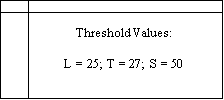


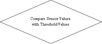


FIGURE 3. Algorithm for the proposed design.
Initially, the threshold values for light intensity, temperature, and smoke is defined and stored in the ARM7 processor. The threshold values represent normal conditions at any given time. The processor collects sensor values from light sensor (LDR), temperature sensor (LM35), and smoke sensor (MQ2) constantly and compares these values with the stored values. The ARM7 processor then controls the devices such as lights, fans, and alarms wirelessly using Bluetooth.
Light Dependent Resistor (LDR)
The threshold illumination is set to 25 lux units. The ARM7 processor controls lights wirelessly using Bluetooth, based on this threshold value. Low light condition is any value below threshold value and bright light condition is any value exceeds threshold value. The ARM7 processor generates alert messages and displays it on the smart device.
Temperature Sensor (LM35)
The threshold temperature is set to 27 degree Celsius. The ARM7 processor controls fans wirelessly using Bluetooth, based on this threshold value. Cold condition is any value below threshold value and hot condition is any value exceeds threshold value. The ARM7 processor generates alert messages and displays it on the smart device.
Smoke Sensor (MQ2)
The threshold carbon monoxide level is set to 50 parts per million (PPM). The ARM7 processor controls fans and alarms wirelessly using Bluetooth, based on this threshold value. The processor turns on fans and alarms if the sensor value exceeds the threshold value. The ARM7 processor generates alert messages and displays it on the smart device.
CHAPTER 6
RESULTS
The proposed smart home system is designed and implemented using ARM7 processor, Bluetooth, and sensors. This system is tested under varying conditions and results are produced using MATLAB code.
Light Control
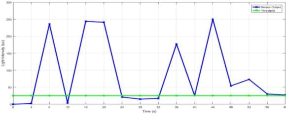
FIGURE 4. Illumination levels captured by the LDR sensor in different lighting conditions
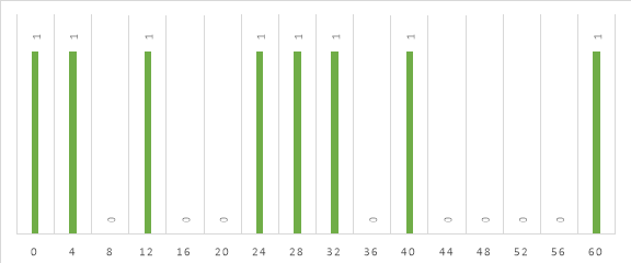
FIGURE 5. Controlling of lights based on LDR sensor output
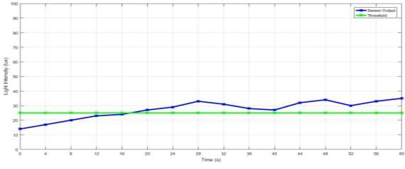
FIGURE 6. Illumination levels remain constant by using this smart home system
In this project, the minimum illumination or threshold illumination is set to 25 lux units. This threshold value is a reference point to decide dark and bright lighting conditions. Figure 4 is a graph of illumination (lux) captured by the sensor, in comparison to the threshold illumination, versus time (s). The brightness is constantly varied to simulate dark and bright conditions. The sensor output is indicated in blue and the threshold value is indicated in green.
Figure 5 is a graph that shows the controlling of lights based on the illumination levels recorded by the sensor in figure 1. Clearly, the light turns on when sensor output falls below the threshold point and turns off when sensor output exceeds above the threshold point.
Figure 6 is a graph that shows the efficiency of this smart home system in maintaining a constant illumination level thereby saving energy consumption.
Fan Control
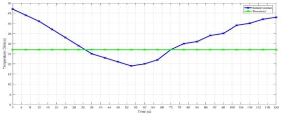
FIGURE 7. Temperature changes captured by LM35 temperature sensor under different conditions
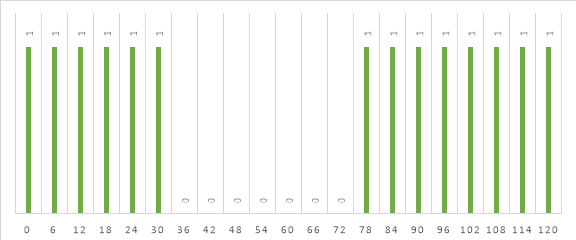
FIGURE 8. Controlling of fans based on the LM35 sensor output
In this project, the minimum temperature or threshold temperature is set to 27o C. This threshold value is a reference point to decide cold and hot conditions. Figure 7 is a graph of temperature (o C) captured by the sensor, in comparison to the threshold temperature, versus time (s). The temperature is constantly varied to simulate hot and cold conditions. The sensor output is indicated in blue and the threshold value is indicated in green.
Figure 8 is a graph that shows the controlling of fans based on temperature variations recorded by the LM35 sensor in figure 7. Clearly, the fan turns off when sensor output falls below the threshold point and turns on when sensor output exceeds above the threshold point.
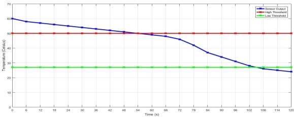
FIGURE 9. LM35 sensor output for extreme temperature condition
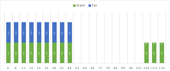
FIGURE 10: Automatic control of fans and alarms based on extreme temperature conditions recorded in figure 9
Figure 9 shows the temperature recorded by the LM35 sensor in comparison to high and low threshold temperature. High threshold is indicated in red and low threshold is indicated in green. Figure 10 shows the working of fans and alarms based on the temperature recorded in figure 9.
When the output temperature exceeds high threshold, alarm is activated or turned on and vice versa. Similarly, when the temperature exceeds high threshold, fan is turned on and vice versa. In this way, this system not only provides automatic control by operating fans but also provides security by turning on alarms to alert the user.
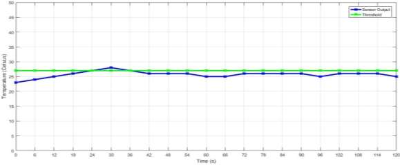
FIGURE 11. Temperature remains constant by using this smart home system
Figure 11 is a graph that shows the efficiency of this smart home system in maintaining a constant temperature level.
Alarm Control
In this project, the minimum CO level or threshold CO level is set to 50 ppm (Parts Per Million). This threshold value is a reference point to decide high and low conditions. Figure 12 is a graph of CO level (ppm) captured by the sensor, in comparison to the threshold level, versus time (s). The CO level is constantly varied to simulate low and high gas conditions. The sensor output is indicated in blue and the threshold value is indicated in green.
Figure 13 and figure 14 show the controlling of alarms and fans respectively, based on CO level variations recorded by the MQ2 sensor in figure 7. Clearly, the alarm and the fan turns off when sensor output falls below the threshold point and turns on when sensor output exceeds above the threshold point.
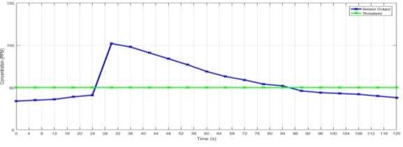
FIGURE 12. CO levels captured by the MQ2 gas sensor under different conditions
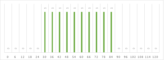
FIGURE 13. Controlling of alarms based on the MQ2 gas sensor output
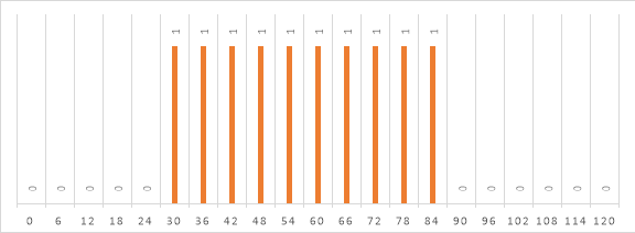
FIGURE 14. Controlling of fans based on the MQ2 gas sensor output
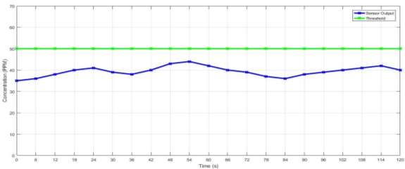
FIGURE 15. Carbon monoxide level is under control using this smart home system
Figure 15 is a graph that shows the efficiency of this smart home system in controlling the smoke levels.
CHAPTER 7
CONCLUSION AND FUTURE SCOPE
Current home automation systems such as X10, INSTEON, ZigBee, and Z-Wave have limitations in the areas of connectivity, transmission speed, interference, bandwidth, and cost of implementation. In this p
Cite This Work
To export a reference to this article please select a referencing stye below:
Related Services
View all


DMCA / Removal Request
If you are the original writer of this essay and no longer wish to have your work published on UKEssays.com then please click the following link to email our support team:
Request essay removal