LNG Markets and Carriers
| ✅ Paper Type: Free Essay | ✅ Subject: Engineering |
| ✅ Wordcount: 2027 words | ✅ Published: 31 Aug 2017 |
LNG Ship Market
Natural gas is a hydrocarbon gas mixture consisting mainly of methane, which is used as an energy source for many applications, such as electricity generation, heating and transportation. It can be considered the cleanest of all fossil fuels, producing up to 29% less CO2 per Joule than oil, and minimal amounts of sulphur (1). Combined with its relatively low price and high energy content per weight, natural gas could have been a viable energy solution many decades ago, but its widespread use was hindered by the difficulty to store and transport it. Nowadays, its majority is transported through pipelines and as liquefied Natural Gas (LNG) by shipment (around 27%). LNG is natural gas that has been converted to liquid form for ease of storage and transport, requiring only about 1/600 of its volume in gaseous state. LNG transportation by ships is used particularly when geographical constraints deem pipeline use unfeasible. An aspect that has held back LNG, and by extension natural gas use, is the very high capital costs associated with the LNG supply chain (gas exploration, liquefaction, transportation and regasification) (2). These required high investments, mandated security of LNG supply and led to long term cooperation between buyers and sellers. This resulted in a highly structured LNG market, with rigid contracts of 20 years or more and very few vessels left spare for use in spot trade. This initial market profile could be characterized as an oligopoly, formed by large state-controlled or regulated oil and gas companies and a small number of independent ship owners. A bad period for the LNG market were the 1980s, where energy prices were high and the demand was low. At the time of the market’s revival (early 1990s) the LNG trade was firmly divided between the Atlantic Basin and Asia Pacific markets. However after the 1990s, with additional liquefaction plants being built in exporting countries and cost reductions in all segments of the supply chain, a surplus of LNG available was created and a lot of new investments were triggered. This led to gradual liberation of the gas market with short term contracts also being signed. However, long term contracts, also known as SPAs (Sale and Purchase Agreements) still dominate the market, as no supplier undertakes a new project without contracting and securing its outlet first. At the moment spot rates represent up to 15% of the total market, with indications that contracts are increasingly becoming more flexible in volumes and price mechanisms (3). The market is also increasingly international, with another major export area being the Middle East. As seen in Figures 1 and 2, Qatar is nowadays the biggest LNG exporting country, with a share of over 25% of world exports. The main importing countries are Japan, Korea, Taiwan, China, Spain, UK and Italy all of which are either countries in need of large energy amounts, or face domestic energy supply shortages (4). Japan in particular, after the Fukushima Daiichi nuclear disaster became an even larger importer, accounting for a third of world LNG imports. China is expected to dramatically increase its LNG imports in order to achieve its goal of decreasing air pollution by doubling natural gas usage for power by 2016 and relying less on coal for energy production (5). Europe on the other hand has seen a decrease in LNG importing in recent years, mainly due to the recent financial crisis and volatile market, and also because of the drop in spot rates and the fact that Asian and American countries are paying more for gas. The outlook on future LNG trade is positive however, as seen in Figure 3 (6), especially when considering the steady and linear LNG market increase up to the late 90s (Figure 4) (7). In terms of the LNG carrier fleet, there are around 380 LNG vessels operating today, with 94 new buildings scheduled for delivery until 2017 (8). In Figure 5, it can be observed that the average capacity of LNG carriers on order is between 150.000 – 160.000 m3 while the average operating LNG carrier has a size between 120.000 – 140.000 m3. This indicates a trend of increasing vessel sizes, in line with what is happening to other merchant shipping markets in recent years.

LNG Ship Structures
The most striking difference between LNG carriers and typical tankers is the complex cargo containment and handling systems found on LNG ships. These serve several purposes. They seal the LNG in a positive pressure, gas tight compartment to avoid mixing with air;Â insulate it from outside heat in order to keep the entire cargo amount at -162 oC, thus minimizing boil-off gas, and also prevent this very low temperature from reaching the hull structure and cause steel brittleness (9). LNG vessels normally have between four and six cargo tanks which are either independent, self-supporting tanks or membrane-type tanks. By default all LNG ships are double hull vessels. Self-supporting tanks are independent to the ship hull and are free to thermally expand and contract. They are also easy to inspect for leakage, but on the downside they do not make efficient use of space (10). The tank type that is typically used on LNG carriers is the Type B independent tank, which is usually spherical (Figure 6). This design, also known as the Kvaerner-Moss System, initially used storage tanks made of 9% nickel-steel, but these were quickly replaced by aluminium tanks which are more resilient to thermal and mechanical stresses are and easier to form. The tanks feature an equatorial ring from which they suspend, and therefore the majority of mechanical and thermal stresses are exerted on that area (11) . Because of their enhanced design, Type B tanks only require a partial secondary barrier in the form of a dip tray. The hold space is normally filled with dry inert gas; however dry air can also be used if the system is capable of providing inert gas to the area in a case of case leakage. A protective steel dome covers the primary barrier above deck level and insulation is applied to the outside of the tank (12). Insulation materials are typically glass, wool, vapour permeable aluminium foil and a number of expansion foam types. Type B tanks can also have a prismatic shape to maximise volumetric efficiency. The other major tank type is the membrane-type tank, with the No.96 System from Gaz Transport and the Mk III System from Technigaz being the main two sub categories. Both types utilize a thin and flexible primary membrane (0.7 – 1.5mm) which is in contact with the cargo and a secondary barrier on the outside. The pressure is applied on the membrane from both the cargo on the inside and the insulation on the outside, and the entire arrangement rests on the ship’s structure, forming an integral part of it. The Gaz Transport 96 system utilizes 0.7 mm thick invar (36% nickel, 0.2% carbon steel alloy) for both the primary and the secondary layer, with boxes filled with perlite used as insulation in between the membranes and in between the secondary membrane and the vessel’s structure. The entire construction leans on each consecutive layer and finally on the ship’s structure (Figure 7). Invar is used primarily because of its low coefficient of thermal expansion which makes the use of expansion boxes or corrugations unnecessary. On the other hand, the Mk III system from Technigaz features a primary stainless steel barrier of 1.2mm in thickness, with corrugations which enable thermal expansion and contraction. Polyurethane foam reinforced with fiberglass is used as insulation, while the second membrane is a simpler and cheaper one, made of triplex, a type of vapour permissible plastic mass. Both systems permit a boil-off of up to 0.15% but in reality this is much less (12). In 1994 Tehnigaz and Gaz Transport merged and their respective systems since bore a GTT suffix in their names. GTT also developed a third membrane containment system for LNG carriers named Combine System One (CSO), which combines elements from both designs (11).
Propulsion Systems using LNG as Fuel
The use of LNG as a propulsion fuel is a relatively new trend for non-LNG carrier vessels. The reason for considering LNG as a fuel for tankers, bulk carriers and ferries is mainly because it is much more environmentally friendly when compared to other types of fuel such as heavy fuel oil and marine diesel oil. This is especially important for vessels operating in emission controlled areas (ECAs), and with future IMO plans of expanding these areas, many ship operators are considering alternative solutions. The option of using LNG offers the benefit of almost sulphur-free emissions, and therefore access to ECAs, at a price much lower than that of low sulphur heavy fuel oil. However, LNG bunkering stations are not very widespread, and the high investment required for propulsion and fuel handling systems is also a deterring factor. Nevertheless, LNG has been used as a fuel on LNG tankers ever since 1964 (13). Early systems utilised steam turbines for propulsion, which were powered by steam produced in boilers that operated by burning the boil-off gas from the cargo tanks. Even though this propulsion type is not very efficient (about 28%), the ability to utilise cargo which would otherwise just be disposed of provided major economic advantages to operators. This type of propulsion system is still found in the majority of LNG carriers up to this day. Nowadays however, because of the relatively high price of natural gas, re-liquefaction plants are starting to be utilised, in order to capture and re-store boil off gas, and slow speed diesel engines burning heavy fuel oil are used for propulsion. This results in significant fuel savings (slow speed diesels are around 50% efficient) but does not solve the ever growing emission problem. Therefore, dual fuel engines are also starting to be used in the industry. These are primarily diesel engines working on the same principle, with the difference that gas is also introduced with air in the induction stroke, and is burned together with diesel fuel when that is injected at the end of the compression stroke. The result is much cleaner emissions and fuel savings. Duel fuel engines can either be direct drive or coupled to generators for electric propulsion. For direct drive systems slow speed dual fuel engines can be used but medium speed engines for electric propulsion are the predominant choice at the moment. Dual fuel gas turbines can also be used for that matter but are not widely utilised on LNG carriers (14). In Figure 9, a distribution of propulsion systems for new LNG carriers on order can be seen.
References
1. Natural Gas and the Environment. s.l. : NaturalGas.org.
2. LNG shipping business versus dry cargo shipping – a comparative study. S.Kamalakannan and Dr.B.Madhavan. 2012, ZENITH International Journal of Business Economics & Management Research.
3. History, trends and prospects for LNG shipping. Leroy, Paul-Albert. Athens : Barry Rogliano Salles, 2012.
4. White, Bill. Alaka Natural Gas Transportation Projects. [Online] 6 September 2011. [Cited: 12 March 2014.] http://www.arcticgas.gov/global-LNG-rapid-growth-overestimated-demand-excess-capacity.
5. Cunningham, Nick. The Diplomat. [Online] 5 December 2013. [Cited: 12 March 2014.] http://thediplomat.com/2013/12/china-increases-purchases-of-lng-on-spot-market/.
6. Kurt Oswald, Joerg Doerler, Akshat Seth. ATKerney. [Online] December 2011. [Cited: 12 March 2014.] http://www.atkearney.com/paper/-/asset_publisher/dVxv4Hz2h8bS/content/the-future-of-the-european-gas-supply/10192.
7. White, Bill. Alaska Natural Gas Transportation Project. [Online] 13 August 2013. [Cited: 12 March 2014.] http://www.arcticgas.gov/alaska-lng-could-have-right-heat-content-asia-buyers.
8. Almeida, Rob. Who’s Building LNG Carriers? gCaptain. [Online] 22 April 2013. [Cited: 12 March 2014.] http://gcaptain.com/whos-building-carriers/.
9. Michael D. Tusiani, Gordon Shearer. LNG: A Nontechnical Guide. Tulsa, Oklahoma : PennWell Corporation, 2007.
10. Zhou, Prof. Peilin. NM952/21525 Advanced Marine Engineering course notes. Glasgow : s.n., 2014.
11. Sacchi, Alan. Types of LNG Carriers. Hrvatsko pomorsko dobro. [Online] [Cited: 13 March 2014.] http://www.pomorskodobro.com/en/types-of-lng-carriers.html.
12. International Safety Guide for Inland Navigation Tank-barges and Terminals. Types of Gas Carriers. ISGINTT. [Online] 2010. [Cited: 13 March 2014.] http://www.isgintt.org/files/Chapter_33en_isgintt_062010.pdf.
13. MAN Diesel and Turbo. Propulsion Trends in LNG Carriers. MAN. [Online] [Cited: 13 March 2014.] http://www.mandiesel.com/files/news/filesof8074/5510-0035-01ppr.pdf.
14. Wartsila. LNG – the Pros & Cons. Wartsila. [Online] June 2012. [Cited: 13 March 2014.] http://www.wartsila.com/en/lng-the-pros-and-cons.
Appendix
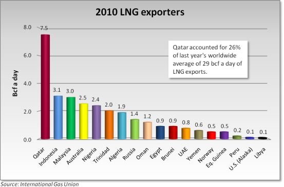
Figure 1: Main LNG Exporting Countries in 2010 (4)
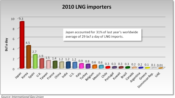
Figure 2: Main LNG Importing Countries in 2010 (4)
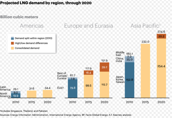
Figure 3: Projected LNG demand by region until 2020 (6)
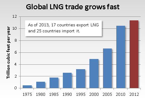
Figure 4: LNG demand up to 2012 (7)
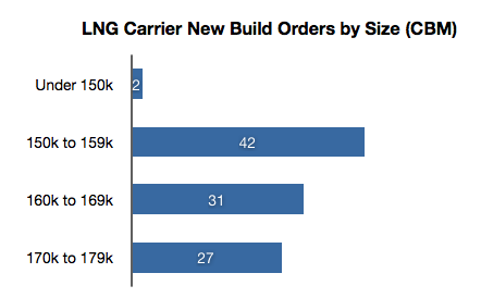
Figure 5: LNG Carrier New Build by Size
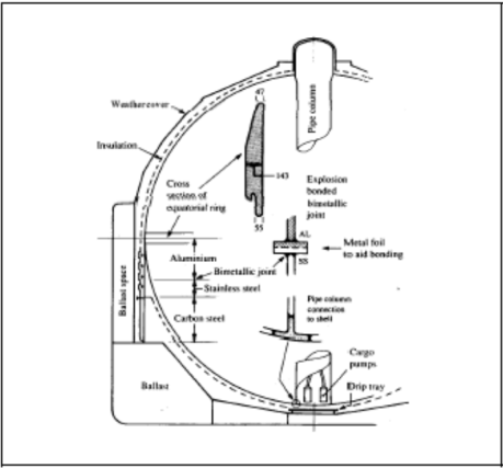
Figure 6: Self-supporting spherical Type B tank (12)
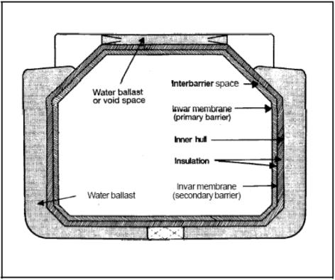
Figure 7: GT 96 Membrane Containment System (12)
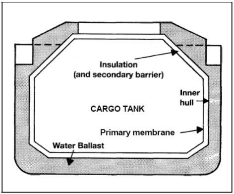
Figure 8: GT Mk III Membrane Containment System (12)
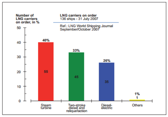
Figure 9:Â Distribution of propulsion systems of LNG fleet on order (13)
Cite This Work
To export a reference to this article please select a referencing stye below:
Related Services
View all


DMCA / Removal Request
If you are the original writer of this essay and no longer wish to have your work published on UKEssays.com then please click the following link to email our support team:
Request essay removal